No its not a switching or a usb charter psu.
How do I use this scope as spektrum analyser.
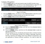
Its a SDS1202x-E.
Don't expect miracles though. It's only 8 bit vertical resolution.
LMGTFY: https://www.manualslib.com/download/2105244/Siglent-Sds1000x-E-Series.html
You'll love that. Page 129.
Jan
You'll love that. Page 129.
Jan
Attachments

It's a nice video, apart from the fact that the guy has no idea what he's doing ;-)
Don't expect miracles though. It's only 8 bit vertical resolution.
Jan
You may be getting some noise through the power input in the supply, or if grounded through the ground via the OSC. You could go differential.
You're starting to get into the territory where the OSC = speed vs 8bit, then compared to the audio spectrum analyser where less speed (1-200KHz roughly - a sound card/USB ADC) and 24bit vs RF spectrum analyser which starts at 9KHz and goes up and up. There's no one tool that does it all.
I have a SDS1202x-e but below 80-100dBV on the FFT I would prefer a differential 24bit ADC acquisition card.
The setup:

My first take on the FFT,but I find it a little strange that the pk to pk changes when I change the amplifud on the scope.That makes it a little hard to get a grip on what is the right value.
And I dont know how to read the FFT to.....

My first take on the FFT,but I find it a little strange that the pk to pk changes when I change the amplifud on the scope.That makes it a little hard to get a grip on what is the right value.
And I dont know how to read the FFT to.....
Yeah - but you didnt show how the scope hooks up to the output of the regulator. I see a load resistor, a red and black wire. Then where's the probe?
As I recall, noise measurements on a power supply are all about how the scope probe connects to it. We'd use a scope probe tip socket, with 1/4" lead lengths on both tip and ground connections. That socket would have been soldered directly across the load resistor leads, as close as possible to the output connector.
As I recall, noise measurements on a power supply are all about how the scope probe connects to it. We'd use a scope probe tip socket, with 1/4" lead lengths on both tip and ground connections. That socket would have been soldered directly across the load resistor leads, as close as possible to the output connector.
Last edited:
Ok the probe is set on the red wire the positive,the wire is about 4-6cm long.Yeah - but you didnt show how the scope hooks up to the output of the regulator. I see a load resistor, a red and black wire. Then where's the probe?
As I recall, noise measurements on a power supply are all about how the scope probe connects to it. We'd use a scope probe tip socket, with 1/4" lead lengths on both tip and ground connections. That socket would have been soldered directly across the load resistor leads, as close as possible to the output connector.
And the crokodile grund is on the black wire.maybe i should connect i on the resistor leads?
One thing that's affected me:
If you have LED lights that use PWM (dimmable ones, basically), turn them off - I've such a panel over my workbench and it generates an absolute ton of noise spikes - I've been checking the noise floor of a microphone preamp recently and had to do this.
If you have LED lights that use PWM (dimmable ones, basically), turn them off - I've such a panel over my workbench and it generates an absolute ton of noise spikes - I've been checking the noise floor of a microphone preamp recently and had to do this.
The best would be a screened BNC wire soldered directly on the load resistor, and the load resistor as close as possible to the PSU output pins.Yeah - but you didnt show how the scope hooks up to the output of the regulator. I see a load resistor, a red and black wire. Then where's the probe?
As I recall, noise measurements on a power supply are all about how the scope probe connects to it. We'd use a scope probe tip socket, with 1/4" lead lengths on both tip and ground connections. That socket would have been soldered directly across the load resistor leads, as close as possible to the output connector.
Connecting the scope ground clip to a ground wire on the input of the supply invalidates any measurement.
Jan
Yes,I have an older probe that I can cut and solder direct on the resistor.
The Light is an old schoool one with no dimmable.
The Light is an old schoool one with no dimmable.
With bandwidths in the ballpark of 100MHz and 8bit ADCs the resolution is quite poor. What you see is noise outside the interesting audio band, often caused by the scope itself. And the numbers you read are pretty useless being unrelated to audible noise. Generally I consider the scope inadequate for audio noise measurements, just the wrong tool for that purpose. Any sound card with a software like REW or ARTA is way better.Yes,I have an older probe that I can cut and solder direct on the resistor.
The Light is an old schoool one with no dimmable.
The old probe cable was broken ,so I removed the shorts cabels from The psu an connected The new probe disrectly to the loadresistor.
And The lowest I can get is about 7mA.
Its flickering betwen 6-9mA.
If I use a soundcardI have to use a resistor devider?
And The lowest I can get is about 7mA.
Its flickering betwen 6-9mA.
If I use a soundcardI have to use a resistor devider?
Yes, and often you need series connected decoupling caps as DC blockers, tooThe old probe cable was broken ,so I removed the shorts cabels from The psu an connected The new probe disrectly to the loadresistor.
And The lowest I can get is about 7mA.
Its flickering betwen 6-9mA.
If I use a soundcardI have to use a resistor devider?
A while ago I built this one https://sound-au.com/project154.htm
But I have not tested it yet.
Is there a dissadvantage that there is a opamp in the signalway?
I mean how much noise does it add?
But I have not tested it yet.
Is there a dissadvantage that there is a opamp in the signalway?
I mean how much noise does it add?
CA3140 is an oldie, and yes, it is noisy. And, btw, for measuremants of amps and power supplies there is neither need for a high-impedance voltager-divider nor for a (noisy) voltage buffer. A passive divider will do. As passive symmetrical attenuator I actually use a fine quality 10k tandem potentiometer (Alps), 100uF/50V decoupling caps polarized for pos DC of class-D-bridge output, and a series input protection resistor between 1k and 10k. My main application are TPA3251 amps powered by 30V DC. For higher power output the values must be re-calculated.A while ago I built this one https://sound-au.com/project154.htm
But I have not tested it yet.
Is there a dissadvantage that there is a opamp in the signalway?
I mean how much noise does it add?
Last edited:
Also you want to keep the impedances in the attenuator as small as possible.
A 10k resistor generates about 1.8uV noise in the audio bandwidth.
And yes, capacitors can generate noise as well!
Jan
A 10k resistor generates about 1.8uV noise in the audio bandwidth.
And yes, capacitors can generate noise as well!
Jan
Jan, do you have information about cap noise generated by electrolythics?And yes, capacitors can generate noise as well!
Jan
- Home
- Design & Build
- Equipment & Tools
- Trying to measure noise With Siglent scope