I dont know what (atm) to use it with,maybe a dac.
It must be 120hz.
It is this psu.
https://www.ebay.com/itm/2842216320...rentrq:e6d3cc2517f0a9d91fd46027fffc0d2a|iid:1
It must be 120hz.
It is this psu.
https://www.ebay.com/itm/2842216320...rentrq:e6d3cc2517f0a9d91fd46027fffc0d2a|iid:1

For ripple and noise, I'd think you'd want the scope setup to capture at least one full cycle at 50/60 Hz - along with the highest sample length (depth) the scope can do. We used to twiddle with the trigger level to get the very highest p-p value possible.
Also be sure to measure (comparatively) the noise with the power switch "off" on whatever is feeding this board. Presumably, earth ground carries through to chassis. It also connects to scope and the (-) lead of your - presumably - single ended probe. Plug the scope into the same strip, next door to the power cord for the power supply running your board. There will still be a ground loop, but it's minimized if you do that.
How to measure noise precipitated endless conversations during my career, with all kinds of technique proposed; how to connect the probe, how to curl the ground wire about the probe tip, scope floating or not, 20 mHz bandwidth industry standard, differential probe with the (+) to power supply output, (-) to ground, break the measurement up into different sweep rates and how to add up the results (root of sum of squares was was ultimately agreed upon). I came up with a method to vary line and load using random values, measure the noise, put that measurement into a pile that eventually looked like a normal curve, then do mean and +3 std dev and compare to the spec limit for a SPC "grade" (Probability of exceeding spec).
I recall from the audio forum at my 1st employer (30 years ago...) one engineer told me he directly experimented with noise injection into +/- rails of an op-amp carrying audio. He said he couldnt hear a thing unless the injected signal was at some ridiculous level , far above what any regulator design would output. This was a private email in reference to a discussion of sonic benefits of shunt regulators people were doing at the time, with measured fractional mV noise and ohms output impedance feeding their op-amp based phono preamps...
It's almost as deep a sink hole as "cables". 1st, you have to measure it right, then you have to design to herculean performance, then you'll hear the difference.
The thing is I am not using a transforme I am using my bench PSU..maybe that could be a problem?

Here it is with the probe shortcutted,and a bandwith limit at 20Mhz.

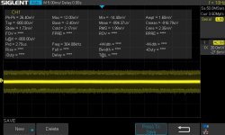
Here it is PSU,the module with a 120mA load. The Pk to Pk value is flickering never still betwen about 10mV to about2mV
Here it is with the probe shortcutted,and a bandwith limit at 20Mhz.
Here it is PSU,the module with a 120mA load. The Pk to Pk value is flickering never still betwen about 10mV to about2mV
- Home
- Design & Build
- Equipment & Tools
- Trying to measure noise With Siglent scope