Mooly - the OP complained that the quiescent current was not stable......
Hi John,
It's not the last word in amp design for sure but against that it has worked for over 4 decades. Once you start swapping transistors around and making circuit changes you need to be super careful. Differences in Vbe between ancient production processes and modern can throw up problems, particularly around bias schemes that are suddenly way out of range for example. All easily fixable but you need to go into something like this with caution so as not to cause damage.
This shows the Miller cap connected for each possibility and finally omitted altogether.
OK, let's see what happens when the configuration is put back as was. With the 100pF capacitor connected C-B rather than C-gnd.
It wasn't clear whether this was originally connected or not from the two diagrams posted - the one with 100nF base shunt omitted it.
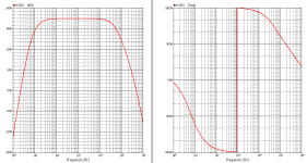
My simulations ran to 100MHz, by the way. Stopping at 1MHz does not reveal some of the quirks.
It wasn't clear whether this was originally connected or not from the two diagrams posted - the one with 100nF base shunt omitted it.
My simulations ran to 100MHz, by the way. Stopping at 1MHz does not reveal some of the quirks.
My simulations ran to 100MHz, by the way. Stopping at 1MHz does not reveal some of the quirks.
Fair enough on that 🙂 but it obviously works (or has worked) well enough in the past.
I think this is quite revealing of stability. 10kHz square driving simulated B&W703. I bet that power amp could sound really good you know. Peak current is -/+2A in the load here.
Hi Mooly
The configuration is stable, I agree. But take a look at the emitter current in the PNP input transistor with your 10kHz square wave input. I can't comment on the accuracy or otherwise of LT Spice versus SIMetrix (which I use), except to say that in my simulations the emitter current exhibits some ringing on the edges. At 3.3MHz where the AC analysis showed a slight peak.
I haven't run a Tian simulation to investigate the gain/phase margins but this type of compenation was widely used in the 1970's as I posted above, typically in Mullard publications too. So yes, in those days it seemed to be "acceptable sound".
So - does your simulation show any instabilities if you swap the NPN driver for a 2N2219A rather than a BC237, or the bias stabiliser for a BD139?
@citizeN - try running your sims without the additional transistor, as Mooly's circuit. In my sims the additional transistor cuts the response down (due to its own frequency limitations) which does suppress the spike.
I may have to apologise for recommending the 2N2219A.
I've just checked the datasheet which says that the BVceo is 40V. Although the BVcbo is 75V, and that is sometimes used as a parameter when using the transistor in a Class AB circuit, it may be that in this circuit, during turn-on, the breakdown voltage is exceeded. It may be that some 2N2219A's are not genuine, as these TO-5/TO-39's are mostly obsolete but some are still sold by "after market" manufacturers.
In which case the BC237B (45V) is a better choice though I would say a 60V TO-39 transistor should have been recommended instead. Not many of those are available, but 2N3019 (80V) was at Farnell last time I looked. Even a BD139 with the leads arranged to fit would have been better (and thermally better too).
So much for my copy of Tower's transistor databook which stated 50V for the Vceo of the 2N2219A.
This may be why the fuse blew in testing.
Back to the original problem - as I requested in an earlier post, what were the voltages when the circuit was powered on?
The dim bulb idea may be helpful as Mooly says. The circuit should tolerate a reduced supply voltage. Not many tungsten lamps available these days either.
Are the output transistors new or original?
There is no short circuit protection other than a fuse and if the transistors are original they may be suffering partial deterioration through age or stress. This could be a possible cause of oscillation.
Last edited:
But take a look at the emitter current in the PNP input transistor with your 10kHz square wave input.
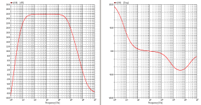
A bit out there 😉 This driving the 'real' reactive load. The output is 'perfect'
If 2N2219A doesn't stand the supply voltage, what about BC141-16, another TO-39 NPN than can cope with 60 Vdc?
Best regards!
Best regards!
John,@citizeN - try running your sims without the additional transistor, as Mooly's circuit. In my sims the additional transistor cuts the response down (due to its own frequency limitations) which does suppress the spike.
My old limited Spice simulator cannot reveal such spikes alas.
But the phaseplot reveals a pole in the MHz-region.
I guess my models are not accurate enough either.
I use BC107, BC157, BC349A, BC161, 2SC734, SD234.
Better have them synchronised with Mooly's?
Attachments
@ Mooly,
At least that seems to confirm a similar result to the sims I ran!
Notice that the first period in the ringing cuts the input transistor off for a fraction of a microsecond. That is of course the basis of Otala's "TIM" concerns, but if the input is bandwidth limited, such as by the transistor ahead of the power amp, this may be of no significance.
It is possible to design an amplifier which exhibits only a single differential spike without clipping in such tests.
@Kay - yes the BC141 would be a good choice if they can be obtained.
For what it is worth, one of the first stereo amps I built was a Mullard design using very similar compensation. It sounded "OK" if not particularly crisp. The construction used BFX84 (60V) VAS and NPN driver, BFX29 PNP driver and 2N3055 outputs (not BDY20!). The TO-5 cans had finned heat clips but I don't remember which transistor was used as the bias stabiliser. It was however attached to the output transistor heatsink using braided leads, so that set the precedent for suggesting that option. I probably used a BFY51 and a TO-5 thermal mount with ceramic insulator and M3 nylon screw.
Another circuit I came across - much later, but from that era - used TIP3055 output transistors and 2N2219A/2N2905A drivers. Not sure exactly what the supply voltage was but it was rated at something like 15 W 8 ohms, so would have been around 35-40V.
I may have to apologise for recommending the 2N2219A.
I've just checked the datasheet which says that the BVceo is 40V. Although the BVcbo is 75V, and that is sometimes used as a parameter when using the transistor in a Class AB circuit, it may be that in this circuit, during turn-on, the breakdown voltage is exceeded.
In between the VCEO and VCBO, the base current goes negative and becomes dependent on both the emitter current and the collector-emitter voltage. That could lead to very interesting phenomena when the circuit isn't designed for it, and many simulator models don't include this region.
Yes, that is why the base resistor becomes important for output devices.
With the classic VAS stage, when the PNP is driven it will reduce the bias on the NPN and vice versa. That seems to be why some published circuits managed to survive with Vcbo ratings rather than Vceo (as long as Vceo was greater than half the supply).
It is a risk though and better to specify Vceo rated devices.
The risk in this circuit would probably be on turning on, when the biases are not fully established, and there could be 40V across the NPN driver.
Many simulators don't even check Vceo let alone the conditions when reverse bias is needed.
Last edited:
I had some time to start again, one channel at a time. Starting with the left channel I put back the BC237B for TR6 and TR4 and removed the BD139. I can only think that there must have been a microscopic bit of swarf which blew the fuse. Checked everything again thoroughly, switched on, and.....
it worked fine!
I then checked the right channel, leaving the substitute BD109 on the heat sink, after checking and measuring that there was no short, and the 2N2219A with its own heat sink. Still nothing, but, when I switched it off using the On/Off switch rather than unplugging the mains plug, there was just enough movement in the body of the switch to move down so that one of the connections underneath made contact with the heat sink of the 2N2219A. A tiny blue flash, a flat pop, and a red face followed. Both TIP41s blew apart, and there was a small black hole in the side of the 2N2219A.
I had spare TIP41s and a 237B for TR4 and TR6, as well as a 2SC734 for TR3. I left off the heat sinks from the 2N2905As in order for it to be as close to original as possible, switched on, and...... it worked fine too! Just as well, since I've now run out of 1A fuses and it's a Bank Holiday weekend.
It currently sounds great, runs quite hot but not excessively so, and I'm going to leave it playing for a good long time while I think about making some enclosures for some Eminence ME12 1008LEs which probably suit it more than the B&C units. The trimmer pot for the right channel doesn't seem to change the sound in the same way as the left does although it measures the same, but I'm inclined to leave it for the moment as it sounds fine.
Many, many thanks for all the help and support - I think I would have given up without it! I will report back after longer testing (with appropriate period music...)
Did you perhaps overbias the amplifier as the reason for becoming too hot? I guess the power devices' idle current should be adjusted to 10 or 20 mA, not more.
Best regards!
Best regards!
I can't now remember the figures from before - I should have noted them down. I know I ended up doing it by ear, so that it was just above the level where distortion started and it sounded good. This is somewhere around 600 ohms on the 1K trimmer, which actually reads around 1K1 on maximum resistance.
I'll look out my copy of Close To The Edge and put it on for you, Kay!
I'll look out my copy of Close To The Edge and put it on for you, Kay!
I'm please you have it working at least 🙂
You will find in practice that a bias setting of even a milliamp or less removes audible distortion. Ideally set it to the 8 milliamps on the diagram by measuring the voltage between these two points. You should see 8 millivolts DC . A very small voltage. Readjust when the amp is hot as the current will alter.
(just noticed I used 0.5 ohms rather than 1 ohms in the simulation)
I'm still puzzled. I checked everything that I could again, and the only difference between the left and right circuits now is that TR3 is BC237B on the left, and 2SC734 on the right. Turned it on again, and the right channel fuse blew (my last one)
Left channel is still fine. My board has single 0.5 ohm emitter resistors instead of two 1 ohm as on the diagram, but otherwise the same. I get 50 mV immediately on start up, rising to 150 mV when warmed up. Measurement taken with no source connected, and no speaker connected. I double checked with another DMM, and got the same results. After 3 sides of records the heat sink is warm but probably not more than 35 - 40 C. When the right channel was working it was almost too hot to touch - I'd say maybe 60 C
If I lower the bias using the trim pot the sound distorts - it is just above the threshold, and at the point at which the sound does not improve if raised further. It sounds good and doesn't get hot (why not, if the bias is too high?) so I'm inclined to try and replicate it on the right channel by changing TR3 to a BC237B
What else could I have damaged with the mains short? The electrolytics look ok, but it's no big deal to change them if they are faulty - I'd just like to know.... All the resistors read the same on both channels (within tolerances) and I'm still baffled by the fact that the trim pot did not change the bias on the right channel although it still measures ok.
Are you measuring the bias between the two points I circled above?
That bit doesn't compute 🙂 Recheck the reading across the two test points. 150mv across 1 ohm is 150 milliamps. Power dissipated in both output transistors would be supply voltage multiplied by that current, so a @ 39 volts it would be nearly 6 watts. It doesn't sound a lot but its enough to heat a transistor up, particularly on a small heatsink.It sounds good and doesn't get hot (why not, if the bias is too high?)
- Home
- Amplifiers
- Solid State
- Transistor amplifier advice