It's really not a fault of your scan quality, but of the drawing itself instead. I'm missing the (dotted?) connecting lines between simultaneously actuated switches that I'm accustomed to.
Best regards!
Best regards!
Hi Kay, looks like posts crossed over again (almost as quick as the 15 Song Album sometimes!)
Yes, you're right about the switches - both are activated together, and the bank of four input selector switches are linked so that only one can be connected at a time. The diagram is a little confusing - they always are to me, as I'm no expert - and the connections from the lower switches cross over the ground line. I'm not really familiar enough with all the conventions of drawing circuit diagrams, which is why expert advice is always welcome!
I'll get photos as soon as I can - later today, I hope!
Cheers!
As it's a 70's amp and probably uses carbon resistors it might pay you to check some critical values. Other posts suggest this wont be the cause of the lack of gain but in the filtering area it could cause problems.
That's for DC stabilisation.But what does R27 (68k) do exactly? It appears to be superfluous.
R21 is for supressing feedbackloop instability when the gain switch is changed.
This is a coupled selector: pressing one releases the others.
Closed loop gain for Tape and Radio (and Ceramic) is 1x determined by R25 (100Ω).
Closed loop gain for Magnetic is determind by the RIAA nets, where R23 take over the role of R25.
Increasing the gain for Magnetic will not change the gain for the other selections.
Curious enough seems the network of C19, C18 and R26 not involved in the RIAA-feedback loop as I assume both spdt switches (the other for R23, R24 and C17) are mechanically connected. Could this be a mistake in the drawing? A picture by the OP of the front selector switches could give some clues about the working.
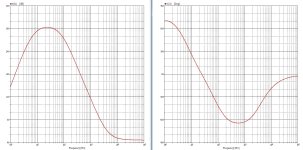
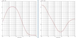
Two plots of the overall gain with (riaa6) C19, C18, R26, and without (riaa3). Hardly any difference and not really compatible with #11 and #13...
For the rest follow #6 and #14.
Attachments

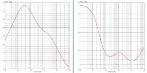
Looking at the MM gain with the 1.2k gain setting resistor, it comes out at 26 dB on the plot below (green trace). However, if you look at the power amp, it seems the gain there is set by a 3.3k and a 68 Ohm resistor (again, I might be reading this wrong because my print out is quite blurry). This would set the power amp gain to 49.5x. The supply rail looks like its 39.5V, so ~800mV needed to drive it to full power. With 5mV on the MM input, you'd be getting 100mV out on IC1A per the green trace so it does seem the gain is rather low if R20 is indeed 1.2k. If R20 is 168 Ohms, the MM gain is 42.4 dB and for 5mV in, you get 660mV out of the preamp stage which seems a bit more in line with the whole gain structure.
If you look at the non-MM inputs, the LF gain is (47k+100+1.2k)/1.2k = 40x which seems too high. The legacy tuner and tape output levels were typically around 200mV - but I'm open to correction here. So I think R24 should be 4.7k and not 47k. That will give the preamp stage a gain of 5x on tape and tuner inputs which fits in with the 40x gain of the power amp.
So something seems not right with R20. and the switches attached to R20.
DC stabilisation already is done with R21 (270k), I think. If drawn correctly, R27 just is a load on the opamp's output.That's for DC stabilisation.
With neither the ceramic nor the MM switch engaged, R25 (100 Ω) in parallel with R21 (270k) is in the NFB path, which yields in a gain of roughly (if R20, 1k2 is neglected) unity (1.083, to be precisely).If you look at the non-MM inputs, the LF gain is (47k+100+1.2k)/1.2k = 40x which seems too high.
Best regards!
The top three switches on the left and the the top one on the right are interlocked I'd say - so, tuner, recorder and ceramic pickup all use the 5x gain. When they are selected, the bottom two switches (MM select an MM EQ attached to C19 are locked out. If you depress the MM button, the previous 4 sets of contacts are opened and the bottom two switches connect the MM.
As already said, I'm missing detailled informations of how the switches work. Anyway, I assume that both switches immediately above the gnd line act simultaneously, hence the R23/R24/C19 is active with ceramic PU's.
Where did you get your gain of 5 from?
Best regards!
Where did you get your gain of 5 from?
Best regards!
R21 (270k) does a some contribution to dc stabilisation, but R27 (68k, approx 1/4 that value) acts directly upon C15 (33u). Hence R27 for dc and R21 for switch-pop suppression.DC stabilisation already is done with R21 (270k), I think. If drawn correctly, R27 just is a load on the opamp's output.
I think the 47 k should be 4.7 k. Then everything except the 1.2k makes senseAs already said, I'm missing detailled informations of how the switches work. Anyway, I assume that both switches immediately above the gnd line act simultaneously, hence the R23/R24/C19 is active with ceramic PU's.
Where did you get your gain of 5 from?
Best regards!
The difference between 47k and 4.7k is only a dot. But compare with R20: "1k2" and not "1.2k".
And those connections of the switches (referring C18, C19, R26), which doesn't make sense.
And those connections of the switches (referring C18, C19, R26), which doesn't make sense.
When does it make sense?
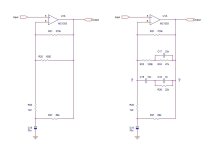
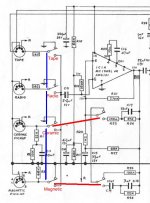
The blue lines represent the mechanical selection of the source, only one permitted.
The red lines are fixed mechenical DPDT switch connections.
So with Tape and Radio the circuit is as shown, R25 in the feedback loop - gain is low.
With Ceramic R23, R24 and C17 are in the feedback loop, R1, R2 and C1 are fixed to its input.
With magnetic, C18, C19 and R26 are the RIAA feedback together with omnipresent R21.
I'll do some ac sweeps soon & post.
Attachments
Radio and tape sources in 1972/3 were c 200 mV - so I’m struggling to understand why the gain would be close to unity rather than 5x. The ceramic input does not use feedback EQ. The network hanging off the ceramic input is the EQ I believe (it’s a capacitive output sensor). So I think all the inputs other than MM close the switch below the 270k resistor.
The little square boxes besides Tape and Radio shows "140", I assume 140mV.
At the output of IC1A it reads "200", assumed 200mV. Line level gain is designed at 1.4 (+3dB) to match dated standards.
The Ceramic input is equalised at the input and sort of boosted in the feedback, "sounds pretty good, not?"
Magnetic is not yet the standard record player (most folks have ceramics with saphire needles), and the 'diamond' clearity is on its own.
A top view picture of the four selector switches will clearify things. T and R are DPDT, C and M are 4PDT (stereo!).
- Home
- Amplifiers
- Solid State
- Transistor amplifier advice