Sorry for the delay, and thank you for all the help! I hope these images are a bit clearer, although some of the markings are a bit blurry and I think there are some mistakes (R10 appears twice)
R24 is indeed 47k, and all resistors that I have tested have been within tolerance. I have replaced a few so that they are as close as possible to design spec (R25 R26)
I replaced R20 with a 680R and the level was higher, so I tried 470R - testing by ear, it still sounded good and better level. I don't have any lower values in my box at the moment, but it may be worth trying even lower?
I don't remember my old amp needing time to warm up (but it was a while ago...) but at the moment setting bias is proving rather delicate. If it is set to sound good from cold, the heat sink (basically an aluminium plate attached to the steel chassis base) gets very hot. If I adjust bias down it then sounds good and runs cooler, but starts off distorted from cold again. I can probably live with that if nothing is being damaged!
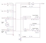
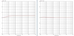
Ceramic response is without input filter!
The (original) MC1303L does not give a GBW-plot, a VCVS is assumed in the simulations.
Magnetic gain will increase with a lower R20, but the open loop gain is limited!
Lower then 470Ω might cause distortion then.
You can use the ceramic input as a line input when R1 is disconnected and C17-R24 is bridged by a wire.
Attachments
1k2 definitely is 1.2kΩ per European conventions!"1k2" and not "1.2k"
We have already stated the comparatively huge gain of 35.3 dB in the power stage.Radio and tape sources in 1972/3 were c 200 mV - so I’m struggling to understand why the gain would be close to unity rather than 5x.
Best regards!
Kay,
"1k2 definitely is 1.2kΩ"
is true, but I used this to enhance the expression of "47k and 4.7k" - 4.7k should appear as 4k7 in the drawing.
🔌
"1k2 definitely is 1.2kΩ"
is true, but I used this to enhance the expression of "47k and 4.7k" - 4.7k should appear as 4k7 in the drawing.
🔌
Oh sorry, now I understand. As I've already mentioned, the drawing lacks to follow some conventions. But which resistor is named with the decimal dot instead of the k in the middle?
Btw, I just spotted some severe error: Please have a look at TR3. Why is it's BC junction short circuited? And, if it weren't, what does the 'lytic C85 in parallel with this junction? How would TR3, the VAS, be driven despite of this capacitor?
Best regards!
Btw, I just spotted some severe error: Please have a look at TR3. Why is it's BC junction short circuited? And, if it weren't, what does the 'lytic C85 in parallel with this junction? How would TR3, the VAS, be driven despite of this capacitor?
Best regards!

That's indeed a flaw in the draw'. C85 being 47nF and the shorting of TR3be (not bc!), and the lack of dotted lines between the switches hints for a trainee while doing it utmost best but never supervised. Times and ages.
In post #42 you mention that the quiescent current appears to be unstable. Is Tr4 mounted on the heatsink of Tr7/Tr8?
Are the drivers (Tr5, Tr6) also on the same heatsink, or have their own - or even none? Or maybe these are on a small heatsink with Tr4?
8mA quiescent current seems low. With 0.5 ohm effective emitter resistors (are these still 1 ohm each?) the quiescent current would normally be around 30-50mA.
The suggestion of BC237/BC307 type driver transistors seems a little underpowered. 2N2905A or BC161 for the PNP and the complements for the NPN (2N2219A, BC141) would be better - or indeed the BD139-BD140 now but the lead configuration would need a little tweaking.
I would have put the 10 ohm resistor in series with the PNP driver collector in its emitter to provide a little better quiescent current stability, loop gain reduction in the PNP/NPN pair and possibly slight improvement in the corssover performance for a quasi-complementary circuit.
The base shunt capactor on the VAS transistor Tr3 (47nF) is quite a frequency limiting slug. It's out of the old school of stabilisation.
Last edited:
TR7 and TR8 are mounted on a heat sink, but all other transistors are on the circuit board with no thermal link between any of them.
The emitter resistors are single 0.5 ohm (I replaced the originals as one had been getting very hot) and I have mostly measured around 25 -30 mA when it has been not too hot and sounding good - but it seems to be a delicate balance. The very helpful man who kindly sent me the circuit diagram said that he had trouble setting the quiescent current too.
One or two of the old transistors were faulty, so I replaced them all anyway since they are not expensive and work had already been done previously (and some things were not the correct values)
The list is now:
TR1 - 2SC 732
TR2 - BC212L
TR3 - BC37B
TR4 - BC237B
TR5 - 2N 2905A
TR6 - BC237B
TR7 - TIP41C
TR8 - TIP41C
I'm happy to do anything I can to keep it cool and stable, and there is something appealing about spending time on something which would not be worth doing commercially, just to keep it going.
Add clip-on heatsinks to TR5 and TR6. Preventing their temperatures from rising will make the bias more stable.
Ed
Ed
I don't know what max ambient temperature commercial goods designer work with maybe some one does. General parts for that use are rated for 0 to 70C which might be a clue of sorts.
Also ST do mot list a C part in their spec sheet. R,O and Y. Y being the highest grain group.
Also ST do mot list a C part in their spec sheet. R,O and Y. Y being the highest grain group.
I had to post the diagram in two parts, and they happened to span two pages of the thread, so the note at the bottom are not too clear.
Note 3 reads: 'If components are changed in the power amplifier the quiescent current shall be reset to 15 mA with RV5. The current is measured through the fuse with the volume control at minimum & the amplifier cold'
Below, it reads: 'Some sets will have the following changes - '
C94 deleted
C18 3n9
C85 100n
C61 1n
C49 2u2 16v
C10 100u 16v
C87 deleted
C96 added 10n disc
Looking at the dc biasing is the junctions of the 1R emiter resistors close to 1/2 supply? I'd assume they would want it to be. It's basicaly set by TR2 and 3 and not sure how much the RV can adjust it.
Last edited:
I would move Tr4 (Vbe multiplier) onto the heatsink of Tr7/Tr8, or what passes for the heatsink. You only need to use thin insulated wires (flying leads) (twisted or in some cases I braid these as that holds them together without ties) but put sleeves over the join and transistor leads to keep insulated. You could swap that BC237B (I assume) for a BD139 which would only need an M3 mounting hole but would need a TO-126 insulator to keep the collector from shorting to the chassis. A simple metal strip (bolted down each side) or even a cable tie might work for the BC237B but use a little silicone thermal compound to make a good thermal connection with the heatsink. If you can't drill any mounting holes or do not wish to mod the case, you could even try gluing it down. Epoxy is OK to just over 100C but nasty if it overheats and gives off toxic fumes, so it is not a decision to take lightly. Not that I expect your amplifier to overheat but jsut to warn. In that case don't use silicone thermal or it won't stick.
I would also recommend (again) replacing the NPN driver (BC237B) with a metal can complement to the PNP driver (as mentioned, 2N2219A or BC141 if you can get hold of (a genuine) one). There are some TO-5 (TO-39) heat clips you could push on. They are a little rare these days, but probably easier to locate than TO-92 heat clips. The TO-5's have lower thermal resistance than the TO_92 plastic, so will stay cooler. Move the 10 ohm resistor in the collector of the PNP to its emitter. That will increase the bias voltage needed, but in doing so will increase the bias compensation with temperature.
Surprising that C85 has doubled. At 47nF it was already "too high", but I suppose the designer did so in order to eliminate C87. The fault in this old style design is the use of large feedback capacitor (c84) without a limiting resistor causing a lot of phase shift which needs a large dose of compensation to stop oscillation.
Still, it seems a commonmethod back in those days.
... and RV5 without a series limit resistor is dangerous. Penny pinching (commercially driven) no doubt. Since the bias voltage needed is about 3 Vbe's then the lowest value of the base resistor should be about 600 ohms so I would have used a 470 ohm resistor in series with RV5. Could still generate a large quiescent current but better than a shorted RV5 if it were inadvertently started at the "wrong" end.
Also, regarding the short circuit in the diagram, I suspect C87 was intended to be grounded, not connected to the base of Tr3. That would have been the classic Miller technique of stabilisation which is not required when using a large base bypass capacitor.
Also, regarding the short circuit in the diagram, I suspect C87 was intended to be grounded, not connected to the base of Tr3. That would have been the classic Miller technique of stabilisation which is not required when using a large base bypass capacitor.
Last edited:
The supply rail is 39 V. Even accounting for output saturation you are going to need 600-700 mV on the input to drive it to full output power. The MM gain is inadequate whichever way you look at it and the legacy inputs require a fan of circa 5.1k2 definitely is 1.2kΩ per European conventions!
We have already stated the comparatively huge gain of 35.3 dB in the power stage.
Best regards!
So quite what is going on here I don’t know. I can only assume the values shown in the diagram are not correct and would be needed to be reworked so sort this amp out.
Well, there's an additional gain stage around TR1 between the volume control and the power amplifier section. How many dB's will it add?
Best regards!
Best regards!
Well spotted! I completely missed that. The gain is c. 5x so that means with a 5 mV input on the MM you will be getting about 500 mV at the power amp input. So I think the 47 k is 4.7 k. That will balance everything nicely.
Me too, previously 😉! Is it R24 (47k) you were referring to?Well spotted! I completely missed that.
So we may say the difference in loudness between CD and phono inputs indeed can be traced back to the much higher ouptput level of a CD player, compared to a tuner or tape device.
In a 1980ies amplifier, made by German manufacturer Dual, I also had to modify one of the line level inputs to avoid huge loudness jumps when engaging the CD.
Best regards!
- Home
- Amplifiers
- Solid State
- Transistor amplifier advice