it has two legs for some reason i am not sure but it does nothing in this case maybe its for something else
Trimmers on these designs are either for bias or centre voltage. You would adjust the DC voltage on the output capacitor (circuit side, not speaker) for a level slightly less than 1/2 the supply voltage. You need an oscilloscope and oscillator to adjust it properly but that should be close enough.
Hi gijser,
Without an accurate measurement on the resistor value and supply voltage you do not know what the test current is with any accuracy. With the meter he has, you need to be close to full scale to get any reasonable expectation of a correct reading. Honestly, you can't get around having a decent meter. That means minimum a Fluke or Keysight well over $100 USD. At least those are in tolerance out of the box. You wouldn't believe how many cheap meters are so far off they cannot be calibrated on all ranges. The range used for calibration is closest to 2 volts with all meters I have seen, unless they are closed case (software) calibrated, then each range should be corrected. We are talking expensive meters again.
I am not selling meters. But it is hard to help someone without reasonable equipment. Try setting bias current with a meter that isn't accurate to 1 mV, your errors are huge because the measured quantity is well below where the meter can give accurate readings. As I said, ignore the last digit on that meter. What can you measure?
on first transistor i measure from both c to b and c to e 22v dc  other one same measurement like 7.5 what is going on ? what should be normal voltage ?
other one same measurement like 7.5 what is going on ? what should be normal voltage ?I suspect something is wrong with the bias arrangement. Unfortunately we don't know what it is. Can you tell us what parts are between the bases of the two driver transistors?
If the trimpot is part of the bias circuitry, it could be the problem. Open circuit?
If the trimpot is part of the bias circuitry, it could be the problem. Open circuit?
In the end, I can't argue with that.Honestly, you can't get around having a decent meter.
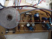
i did a lot of measurements i also found two 1,5ohm resistors i put in there its more then needed but i hope thats not a issue. also it seems like on one side of the board i have 20+ volts and on other like 8 why is that only thing that i did not change are caps but i dont knwo if that can do this let me know. so adjusting the pot do change voltage but only for one side
when i power it up with music for a second it had clear audio and then distortion strange, is there any way to test caps without meter my meter does not have that function
1. Which side does the pot adjust voltage for?
2. You now have 1.5 ohm resistors where you previuosly had the wire around a resistor, right?
3. If yes, measure the voltage across each of the 1.5 ohm resistors and report back.
2. You now have 1.5 ohm resistors where you previuosly had the wire around a resistor, right?
3. If yes, measure the voltage across each of the 1.5 ohm resistors and report back.
i dont understand that part about measuring resistors. thes are replacement for old ones with wire, i had two new 1.5ohm and i used them, adjusting the pot works both ways but a minor change it does not fix my problem
Place one lead on one end of the resistor and the other lead on the other end of the resistor with the meter set to read DC Volts. At this point, don't worry about red and black leads.
Hi sg97,
You are our hands, eyes and nose here. Also, brain.
You need to learn enough to help us help you. It is so difficult and time consuming to try and help this way, and if you misunderstand something and report the wrong information back, it sends everyone down the wrong path.
Servicing electronic equipment is not as easy as it may seem to you. When I have something on my bench, I use all my senses and experience to point me in the right direction before even plugging it in. Once power is applied, the amount depending on what is happening, I make choices as to what to check next and that guides my efforts. Without a circuit diagram, we are all in the dark. There are some things we can check, but I know I have suggested things and you didn't follow through. Same for others.
I'll say it again. Use your meter, test some known good transistors and get a feel for it. Then, look up the parts to see what they do and gain at least a tiny understanding of how a part (whatever it is) works. Learn the symbols for the parts, and help everyone, including yourself, fix this amplifier. You'll gain valuable knowledge and the logic behind troubleshooting will help in all aspects in your life and work.
To make a schematic, we need to know what trace connects to which terminal of each component. For a transistor, that would be the base, emitter and collector. Diodes have an anode and cathode, capacitors often have a positive and negative terminal. If you could at least draw out where the parts are on the board, then draw lines to show where the foil on the back connects to, that would give us a fighting chance. Use your meter on continuity test to confirm what you have drawn - then show us.

- Home
- Amplifiers
- Solid State
- transistor amp not working after shorting output