Those meters will be highly inaccurate at resistances of 1 ohm and lower (and that is being nice). Hugo's suggestion of 0R47 is reasonable given the circuit. Common emitter resistors values are 1 ohm, 0R47, 0R33, 0R22 and 0R1. With such a simple circuit, I would err on the high side and 0R47 feels right.
When making resistance readings that low, you would have a lower full scale value for starters, and a meter that can compensate for lead resistance properly, or use a Kelvin connection (4 wire resistance readings). Look that up please. I use an HP or Keysight meter in Kelvin mode to take readings that low. No offense, but anything you read on your meter is pure fantasy, wildly inaccurate. Your meter simply is not designed for accuracy for starters, and low resistance readings require a more expensive meter with a lower full scale reading (like a 19.99 ohms fulls scale range).
When making a reading with your (and many readers out there) meter, ignore the right hand digit. I am certified to calibrate electronic instruments, and if you calculate your errors given the specs with the meter, you'll understand. That is assuming it was in spec new (most are not) and there are time from calibration and temperature terms as well. It really helps to mentally say to yourself, it's about (your reading) instead of copying down the digits. Once you buy and use a better meter (over $300 US, Fluke or Keysight), you can begin to rely on the reading. Mine are a lot more expensive and not because I want a more expensive meter. It's because I need the readings to be accurate.
You can of course make your own milliohm meter using a steady power supply and a resistor of known value (1k?) in series with your homemade resistor.. and ohms law.
i used those resistors that i made and amp is working but this time bulb is glowing and music is not really loud but louder then before
also one of transistors is not worm and other one is, should i try it with only one transistor ?
Hi gijser,
... and to what accuracy? How stable? How about the voltmeter used to calculate the drop and measure that resistor that sets the current?
This is an answer out of a textbook type situation, not practical at all.
Hi sg97,
You are drawing excessive current, no surprise there. The next step is to reduce the current in th output stage, that is called bias current.

w
what should i do ? for now resistors are not acting strange so what are next steps ? i hear that it had some power but its like its choking (music on putput)Hi gijser,
... and to what accuracy? How stable? How about the voltmeter used to calculate the drop and measure that resistor that sets the current?
This is an answer out of a textbook type situation, not practical at all.
Hi sg97,
You are drawing excessive current, no surprise there. The next step is to reduce the current in th output stage, that is called bias current.
Simple.
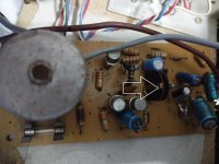
Now it's time to figure out how the bias current is generated. Let's put some effort into tracing the circuit in this area. You have it working, it just isn't fixed completely. Normally there would be a bias control, but not here. That means some fixed components are used. They may have been changed from their proper values earlier, and given what the board looks like I am not surprised one bit.
Now it's time to figure out how the bias current is generated. Let's put some effort into tracing the circuit in this area. You have it working, it just isn't fixed completely. Normally there would be a bias control, but not here. That means some fixed components are used. They may have been changed from their proper values earlier, and given what the board looks like I am not surprised one bit.
i know xddd but i need you guys to tell me exactly what i can do a simple solutions if is possible
... and to what accuracy? How stable? How about the voltmeter used to calculate the drop and measure that resistor that sets the current?
This is an answer out of a textbook type situation, not practical at all.
This actually works in practice. Look here for example: https://www.robotroom.com/Measuring-Low-Resistances.html
But maybe a bit too far fetched for sg97.
Back to the subject, are you using the original output transistors or new, known to be good ones?
I would think the trimpot is to adjust bias, what else is it for?
Anatech is right, you need to figure out how the biasing works. What is this trimpot connected to?
- Home
- Amplifiers
- Solid State
- transistor amp not working after shorting output