From transformer there is bridge recrifier then capacitor, from the capacitor there are two wires that go to the amp , one is + ,one is - ( ground). Wire one leg of each capacitor togheter on the ground, where the - comes from the big power supply capacitor. Then the other two legs of the caps one on each transistor collector ( case , heatsink).up there is input connection maybe i can use its ground ?
Attachments

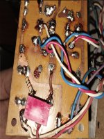
See the negative on the main filter capacitor? Where that goes, or something close to it on teh board.
Not the signal ground!!!
Not the signal ground!!!
i did it on main ground and no effect, i will try to change input pot it acts strange and i will report if other one i have will make a difference
btw on other pot i added when i touch one of 3 connectors it works perfectly so i should ground that but where ?
btw i think that i have not wired input pot the right way. i have old pot its not like new 10k ones, i dont have any new at hand but i dont know if i wired it right way
I'll ask again:
Please post a picture of the input pot, wiring, TRS and connections to the amp.
It could be RF but if the hum disappears with grounded input (pot at 0) I would suspect a problem at the input connections.
This is how the pot should be wired:

The black trace is your ground connection:

Where is that 1k resistor going? To the input pot?
Please post a picture of the input pot, wiring, TRS and connections to the amp.
It could be RF but if the hum disappears with grounded input (pot at 0) I would suspect a problem at the input connections.
This is how the pot should be wired:
The black trace is your ground connection:
Where is that 1k resistor going? To the input pot?
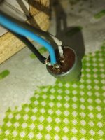
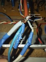
as i said before it is not usual potentiometer, it only work when wired in this configuration i tried other ways but this way it only amplifies. input jack is labeled in picture 2 it is trs female plug i made it to be mono , it is ok btw
Attachments
also i power the amp without pot and buzz is still there so something is not grounded a input i think
if i remember well old case for this amp was all metal and pot was grounded to that , i dont want to do it, i want it to be grounded proper way
Take your ohm meter and measure the pot.
Between two of the tree pins you should measure a fixed resistance, no matter how you turn the pot.
Attach one of them to ground and sleeve from TRS,
the other to tip from TRS.
The third one is your output to amp in.
Ref. post #853
Between two of the tree pins you should measure a fixed resistance, no matter how you turn the pot.
Attach one of them to ground and sleeve from TRS,
the other to tip from TRS.
The third one is your output to amp in.
Ref. post #853
- Home
- Amplifiers
- Solid State
- transistor amp not working after shorting output