Hi X,
how thick is your silicone insulation under the chip-heatsink and what's the W/mK ratio of it? Using 10 mm spacers I would get a gap between chassis and heatsink thicker than my Keratherm sheet, so the plan is now deleted. The height of the heatsink with the chip is 9.5 mm so I think I need a thicker insulation, about 0.6-0.8 mm. I could get a set of 20x67 mm silicone thermally conductive sheets for cpu etc. with a thickness of 0.5-1-1.5 mm - would it be okay?
Thanks for any hint.
Last edited:
I used 1mm thick blue silicone sheets for GPU coolers. It can’t be ceramic because there needs to be compliance to allow the stack up height to float a bit.
Something like this:
https://a.aliexpress.com/_mOzc2Qg
That chassis of yours is looking really nice. The layout looks very familiar! 🙂
Something like this:
https://a.aliexpress.com/_mOzc2Qg
That chassis of yours is looking really nice. The layout looks very familiar! 🙂
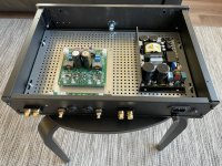
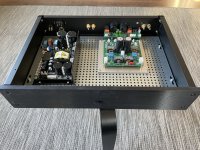
I purchased a Pesante 2U chassis and a friend helped me in drilling out the holes on the front and rear panels. Per X's recommendation, I mounted the amplifier on a 1/4 inch thick Aluminum sheet and bolted that down to the Pesante's base plate. Now that most of the mechanical work is complete, I have to wire up everything.


@Plott, I think you really enjoy the sound of this amp. Can't wait to hear your impression and assessment. Next to my 'First One' amp I built a few years ago, this one is next to the top. X did a fine job with this amp.
Thanks Redjr!
This amp is still one my main “daily drivers”.
A review of the Warp-1 will be coming out in Stereophile soon.
This amp is still one my main “daily drivers”.
A review of the Warp-1 will be coming out in Stereophile soon.
Yes, I think too that I will enjoy it 👍 glad to read you like it that much!@Plott, I think you really enjoy the sound of this amp. Can't wait to hear your impression and assessment. Next to my 'First One' amp I built a few years ago, this one is next to the top. X did a fine job with this amp.
The missing parts of the chassis (two-piece front plate, cover) will arrive tomorrow, so maybe I can finish it this weekend, I'm really looking for it.
Yesterday I hooked up the AC mains wiring (IEC inlet - fuse holder - mains switch - psu connector) with an 11 awg Elecaudio OFC wire with silicone insulation. Surprisingly no issues with this thick wire in the board connector (picture will follow).
Hi X,
how thick should be the aux-wire (+/- 15v)? I think 16 ga is only necessary for the amp board - and impossible to use it with the small aux-connector.
Thanks in advance!
how thick should be the aux-wire (+/- 15v)? I think 16 ga is only necessary for the amp board - and impossible to use it with the small aux-connector.
Thanks in advance!
Hi X,
I had some confusion until I read (again) the instructions for the SMPS.
Obviously, my SMPS has a slightly different configuration without DC-Error connector for an led (yellow circle in the picture of your amp, and I think it´s rather a PSU error connector) - instead there is an led on my SMPS board, so I can´t (?) use a PSU error led on the front panel (too bad that the front panel is already finished).
The DCER connector (red circle) of the SMPS is a trigger input where it takes a signal from the amp in case of a critical error of the amp and the SMPS goes in PROTECT mode - in your case this connector is not used (?).
Any idea how I can display the PSU error on the front panel (I know, with optical fiber from the led on the board 😀)?
 🖖
🖖

