That result with W191 and W194 connected is at least a lot more satisfying as all channels now have the exact same voltage gain, ~7.5 db. Maybe because it is in SE mode?
.png")
Btw, it makes me happy to see that someone finally put the IC on the right side of the board as well as used the right kind of inductors. 🙂

Yes, absolutely. Those are the main signal jumpers. Needed to keep the board 2 layers. It was hard to see that on your board since buried in between the tall box caps.
For reference: Here are photos of a working (verified) amp used in the latest Warp-1 rev04, without the buck converter. But W191 and 194 always have to be installed.


For reference: Here are photos of a working (verified) amp used in the latest Warp-1 rev04, without the buck converter. But W191 and 194 always have to be installed.
Last edited:
In the TI application note on PFFB, they show a plot that clearly shows the effect of using two grades of inductors. The CoilCraft SER’s spec’d here are rated for 30A and hence, contribute very little to the distortion of this amp.Btw, it makes me happy to see that someone finally put the IC on the right side of the board as well as used the right kind of inductors. 🙂
The funny thing is, the CoilCraft MA5172-AE used by TI (toroidal ferrite core), actually cost more than the SER2915-103.
Yep, I am very aware of this myself and this is one of the few things where really the magic happens with Class-D amplifiers 🙂In the TI application note on PFFB, they show a plot that clearly shows the effect of using two grades of inductors.
As a (rough) rule of thumb, use the inductor current rating as the PEAK rating for audio.
So for 100W @ 4ohm = 5Arms -> 7A inductor needed.
The SER1390, SER1512, MSS/MOS series are also great, so are Sumida inductors 🙂
Avoid soft saturation molded inductors like the plaque.
(yet you see them everywhere unfortunately 🙁 )
Hey Boris,
I assume all is good now? How does the amp sound? You are one of the few people who are using this as a 4 channel SE amp.
I assume all is good now? How does the amp sound? You are one of the few people who are using this as a 4 channel SE amp.
I finished my amp today, but unfortunately not successfully 🙁. I’m assuming my problems are in the BTSB since the power supply and amp were RTR.
While I get green lights on the amp and power supply with no fault lights, I get both a minor scratchy turn on and off thump (with the 2200uf cap on the 15v terminal), no sound from the left channel and very distorted sound from the right. I know the speakers work and swapped them between channels, I know my source works of course with other amps, and I get AC voltage out of the BTSB on both channels but that’s as far as I got. Probably the next thing I could check would be to see if 12v is making it to the opamps…assuming they run on 12v.


While I get green lights on the amp and power supply with no fault lights, I get both a minor scratchy turn on and off thump (with the 2200uf cap on the 15v terminal), no sound from the left channel and very distorted sound from the right. I know the speakers work and swapped them between channels, I know my source works of course with other amps, and I get AC voltage out of the BTSB on both channels but that’s as far as I got. Probably the next thing I could check would be to see if 12v is making it to the opamps…assuming they run on 12v.
Hi Soundwavesteve,
I am sorry you are having issues with your amp. I suspect it may be some cold solder joints or solder bridge shorts on the BTSB where you soldered the opamps. Please use some copper braid and liquid flux and a chisel tip iron to clean up the joints and reflow with some fresh solder. Use solder paste with an iron if you have it. It needs to form a clean joint. You can check by connecting headphones or RCA to the single ended outputs and have a listen to make sure it plays music. I know you amp board works because that was tested before it shipped. I assume you have a resistor installed on the bottom side where the layout error is and they cross? Please see picture below with what I think are suspect solder joints. Once the BTSB is working properly, connect to amp. The BTSB should always be on once you provide power to the SMPS630-SO (before enabling it). It needs +12v always on. The BTSB needs to be on when the amp PSU is enables using the SMPS enable trigger. If the BTSB is powering on and off with the 51v of the main output, that will cause thump from the opamps.
Good luck!
X
Haven't listened yet. I changed the input resistor of the NE5532 to 5.6kΩ, so the gain is now ~20dB. I don't really understand why so many PFFB vaules are different from the design document. Rzobel it states should be 1Ω instead of 3Ω and Czobel should be 220nF instead of 10nF.Hey Boris,
I assume all is good now? How does the amp sound? You are one of the few people who are using this as a 4 channel SE amp.
Attachments

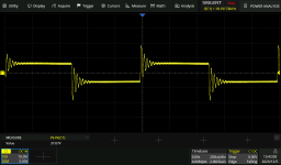
So the missing wire jumpers was the issue all along then. Glad you got that fixed. You are using a 5.7k vs recommended 2.7k resistor. This gives you more gain at 20dB but I wonder if this has something to do with the excessive ringing.
The Zobel with 0.01uF and 3.3R was used in the orginal reference design from TI prior to the PFFB implementation. We added PFFB but didn’t change the Zobel and it seems to work fine. I don’t recall large ringing traces like what you have on your scope shot.
You are welcome to change it to the value on the PFFB app note (about 7x lower RC frequency).
Here is reference design (EVM) application note:
https://www.ti.com/lit/df/slar129a/slar129a.pdf?ts=1701790206719
See page 2 schematic.
No, I changed R105,R115, R117, R107. These are make the opamps double the voltage, but have nothing to do with PFFB, as the feedback is given after the opamp stage. I attached a screenshot of a chinese tpa3116 board, kind of similar ringing.You are using a 5.7k vs recommended 2.7k resistor.
Attachments
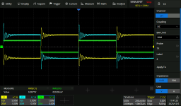
Where is this measured, directly at the output of the IC ?No, I changed R105,R115, R117, R107. These are make the opamps double the voltage, but have nothing to do with PFFB, as the feedback is given after the opamp stage. I attached a screenshot of a chinese tpa3116 board, kind of similar ringing.
Thank you for your reply to my question XRK. I haven't worked on it yet, but I will certainly post back when I do. 👍
I started working on the chips as suggested but part way through I figured I should test voltages and see what was happening there…
And I wasn’t getting 15v anywhere on the board. I was getting +12v coming in, but less than 1 coming out. + or -. And that’s also when I discover that I have continuity between +15v pin and ground. Pretty sure that’s not supposed to happen so I must have a short to ground somewhere but haven’t found it yet.
And I wasn’t getting 15v anywhere on the board. I was getting +12v coming in, but less than 1 coming out. + or -. And that’s also when I discover that I have continuity between +15v pin and ground. Pretty sure that’s not supposed to happen so I must have a short to ground somewhere but haven’t found it yet.
Yay! A working amp! All of my troubles were related to unseen solder bridges under the opamps.
I do still some noise upon turn on and off even with a 2200 50v cap shoved into the 15v socket that powers the D amp driver circuit. Would also powering the standby switch’s LED from the same +-15 source be related? I tried hooking the LED up to the +12v Standby socket but apparently this particular led switch needs + and -, not + and ground.
I do still some noise upon turn on and off even with a 2200 50v cap shoved into the 15v socket that powers the D amp driver circuit. Would also powering the standby switch’s LED from the same +-15 source be related? I tried hooking the LED up to the +12v Standby socket but apparently this particular led switch needs + and -, not + and ground.
Great news!
The LED should not matter where it is connected unless it is more than an LED? I have never heard of an LED in a switch that needs +/- and not +/GND. All it knows is current from + to - or + to GND.
The main culprit to turn on off thump is if the opamps turn off or on when the amp main power is active. Is your BTSB +12v supply connected to the always on power?
Please give me the mfg and part number of your switch or a link to a datasheet.
A working amp = early Christmas gift to myself 😋
Yes, the BTSB is hooked up to the always on 12v. It is minor but it is there, kinda scratchy pop not a thump. Like turning a radio on.
The switch is a generic thing I got on Amazon: 12v LED Switch. I even tried wiring the led direct to the 12v always on, but it wouldn’t light. Then I hooked it up to a +/- power supply as a test and it lit up just fine. So I hooked it up to the 15v aux and it continued to work. I was a little baffled myself but assumed there must be something inside the switch housing to make it act like that. 🤷🏻♂️