Hi Francisdumas,
Good to hear that it’s working well with the Connexelectronic PSU!
Enjoy your amp!

Good to hear that it’s working well with the Connexelectronic PSU!
Enjoy your amp!
Hi Rtep,
What’s the purpose of having the THAT1646 balanced line driver if the BTSB already has a balanced line out via the LME49724 already? ....
That was my thought too. Seems redundant.
Hello guys, sorry that I don't answer so long time but I had a lot of work.
So when I would like to connect the RCA input into the BTSB what I need to do when I want balanced output? The neg_input from BSTB connect to ground? Because I all the time thought that LME49724 need positive and negative input and works as only as a spec amplifier.
So when I would like to connect the RCA input into the BTSB what I need to do when I want balanced output? The neg_input from BSTB connect to ground? Because I all the time thought that LME49724 need positive and negative input and works as only as a spec amplifier.
connect the RCA center to +, shield to -. The better way to do it is with 2 wire + shield mic cable. Then you would connect RCA - to the - wire and shield at the RCA connector side. At the BTSB input connect RCA + to BTSB +, RCA- to BTSB - and shield to the X input.
I think Jhofland explained they input to the BTSB. On the BTSB output, there are 3 pins. The middle one is GND on both BTSB and TPA3255 balanced input. The two on the side are +ve and -ve phase out. Pin 1 (square pad) is +ve phase. On TPA3255 board, The +ve input for Ch1 is A_input and -ve is B (pins on either side of middle pin) and for Ch 2, +ve is C and -ve is D. Just make sure phase is not flipped on one otherwise you won’t have much bass.
Are the PCB mounting hole dimensions documented anywhere please? I need to drill a chassis to fit.
Are you referring to the BTSB, or TPA3255 board? For the BTSB, according to my physical measurements... I get;
91mm x 79mm
Maybe x can confirm.
91mm x 79mm
Maybe x can confirm.
Thanks, DrMordor,
I think I’ll leave the amps up to the user to buy/make. Although I could make a nice linear PSU for it using a single rail SLB and fat 400VA trafo.
I think I’ll leave the amps up to the user to buy/make. Although I could make a nice linear PSU for it using a single rail SLB and fat 400VA trafo.
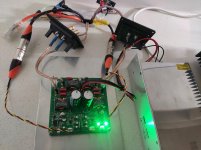
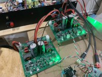
I just verified that the Master/Slave mode for frenquency sync between two amps works well. Just need a WR-WTB 1mm pitch connector cable from Wurth. On slave amp, flip DIP switch to slave. That’s it.

These are the parts you will need from Mouser:
2x of WR-WTB female connectors 710-665003113322
2x of WR-WTN precrimped 12in wire assemblies 710-665165128130
Connect pin 1 to pin 1 and 2 to 2 for same polarity sync and flip for negative polarity sync.
These are the parts you will need from Mouser:
2x of WR-WTB female connectors 710-665003113322
2x of WR-WTN precrimped 12in wire assemblies 710-665165128130
Connect pin 1 to pin 1 and 2 to 2 for same polarity sync and flip for negative polarity sync.
Attachments
Was there a consideration for other output inductors, e.g. Wurth? Are the ones selected sufficiently flat through the useable I(A) curve?
The CoilCraft inductors are the single largest cost of the BOM at about $24 for 4. The SER series selected are good for up to 30A. The data sheet for the TPA3255 says that the max current limit is 17A (set by 22k OC_ADJ resistor), so the inductor is operating well within its design range. I have used Wurth good for 100A before on other amps but don’t think necessary here. Based on the measurements of this amp coming in 2x less THD vs the factory Texas Instruments EVM implementation with PFFB, I think we can safely say that the Coilcraft inductors are not limiting the performance.
Last edited:
- Home
- Group Buys
- TPA3255 Reference Design Class D Amp GB