doctormord,
Is there a schematic of your board you've developed, I haven't found it in the thread, perhaps I missed it somewhere. Are you using the evaluation board values or have you made changes to that? Any information is helpful if you can share it.
Steven
Is there a schematic of your board you've developed, I haven't found it in the thread, perhaps I missed it somewhere. Are you using the evaluation board values or have you made changes to that? Any information is helpful if you can share it.
Steven
doctormord,
Is there a schematic of your board you've developed, I haven't found it in the thread, perhaps I missed it somewhere. Are you using the evaluation board values or have you made changes to that? Any information is helpful if you can share it.
Steven
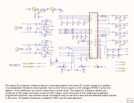
Share our G3H amp unit schematic,altium designer file type.
Attachments
authlxl,
Thank you for the schematic. I assume this is your design and not exactly the same as Dr. Mord's but perhaps I am mistaken.
I was reading the design notes about the output inductors, has anyone checked the distortion of the Coilcraft inductors as maximum output for distortion, do those meet the requirements for linearity that are noted in the TI blog about that?
Dr. there is a blog on the TI site talking about the output inductors by someone at TI and suggesting that you check the linearity of any inductors used and the power level the amp is used at over time.. I'll find the link and post it so you can make any comments.
Haven't you read the post about recommend inductors earlier in the thread from some days ago? As long as your inductors doesn't saturae, distortion is ~like on the EVM. For the Coilcrafts, just check the "Current vs Inductance" from their inductor series website. You want hard saturating inductors for best performance.
As said, self wound on 106-2 toroids should/will perform same like the Coilcraft MA-5172.
As said, self wound on 106-2 toroids should/will perform same like the Coilcraft MA-5172.
This is a difficult question. An apparatus as I understand it works on its own. That can be a powermodul with integrated power-supply, for instance.Voltwide,
Why would his board be different than any other diy project? Wouldn't this just be considered a component of a finished product, not a complete finished consumer product? I'm not from Europe as you can see so I'm just wondering why this would be different than what Dr Mord is doing if it is intended for the diy crowd.
Doctormords pcb requires an external power supply, so it is no apparatus and no CE marking allowed to it.
That is my understanding, maybe I am wrong.
Thanks Dr. I did read that section where different inductors were being discusses but didn't know if they werel selected for a lower power output level. I think you settled on the Coilcraft as being your choice inductor, I just didn't know if the coils you would use for four separate channels would be your same selection if you did a BTL or PBTL configuration.
Voltwide,
I understand what you are saying and can see how separating the power supply from the amplifier section would make things simpler as far as importation and not needing the certification.
I understand what you are saying and can see how separating the power supply from the amplifier section would make things simpler as far as importation and not needing the certification.
Thanks Dr. I did read that section where different inductors were being discusses but didn't know if they werel selected for a lower power output level. I think you settled on the Coilcraft as being your choice inductor, I just didn't know if the coils you would use for four separate channels would be your same selection if you did a BTL or PBTL configuration.
If other vendors do provide same/better performance for a good value, i would take them.
I simulated THD vs. inductor-type/core material/saturation in the past.

The SRP1245A is a soft-saturating carbonyl powder core,
https://www.bourns.com/data/global/pdfs/SRP1245A.pdf
while the VER2923 is a hard saturating ferrite core:
Coilcraft VER2923 High Current Power Inductors
The simulation doesn't take high output levels into account, it's just THD=f(f).
Measurements for 2 different inductors at 2.83V into 4R7:
MSS1278:
And Ice inductors:
These measurements where provided by 5th element. In the end, with substitution of some ceramics for wet electrolytics and ice inductors, it went like this:
From the plots you can see, that core material/inductor construction highly affects thd performance. Changing ceramics for wet electrolytics or foil improves performance in the low frequency range (<200Hz), you will have to decide for yourself if you need ultra low THD for lf/bass.
Attachments

Last edited:
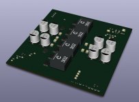
Having some more "boost" on mobile PA ain't cheap.
9-14V -> 38V - 4 Phase
20-33.6 -> 38V - 2 Phase (51V for the 3255)
Having the TPA3255 in mind, the board should handle 600Wrms or 1200Wpeak "continuously". (Design goal - 25A per Rail)
WIP:

9-14V -> 38V - 4 Phase
20-33.6 -> 38V - 2 Phase (51V for the 3255)
Having the TPA3255 in mind, the board should handle 600Wrms or 1200Wpeak "continuously". (Design goal - 25A per Rail)
WIP:
Attachments
Last edited:
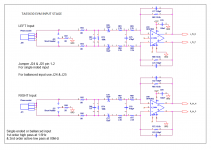
Small critique: If you're using a fully differential amplifier like the OPA1632 for single ended to differential conversion, you need to ensure the input impedance of the source is balanced. Otherwise CMRR will be poor, and a common mode DC offset on the input of the amplifier will cause a DC offset on the amplifier output. See pages 19-20 of this appnote:Share our G3H amp unit schematic,altium designer file type.
http://www.ti.com/lit/an/sloa054d/sloa054d.pdf
You can't depend on the customer to keep the input impedance balanced if they're using a single ended source, and especially if they do something like put a volume pot between their source and the map.
I solved this on my "Wiener Pro" card using a fully differential instrumentation amp design, which handles unbalanced input impedance well and provides good CMRR. If you use this circuit, shove "thanks gmarsh" somewhere on a copper or silkscreen layer 😉

A couple other design options would be to use a dual op amp for each input (one used as a "classical" differential amplifier, and one inverting amplifier), or stick with a single ended input and use a DRV134 or something.
Small critique: If you're using a fully differential amplifier like the OPA1632 for single ended to differential conversion, you need to ensure the input impedance of the source is balanced. Otherwise CMRR will be poor, and a common mode DC offset on the input of the amplifier will cause a DC offset on the amplifier output. See pages 19-20 of this appnote:
http://www.ti.com/lit/an/sloa054d/sloa054d.pdf
You can't depend on the customer to keep the input impedance balanced if they're using a single ended source, and especially if they do something like put a volume pot between their source and the map.
I solved this on my "Wiener Pro" card using a fully differential instrumentation amp design, which handles unbalanced input impedance well and provides good CMRR. If you use this circuit, shove "thanks gmarsh" somewhere on a copper or silkscreen layer 😉
A couple other design options would be to use a dual op amp for each input (one used as a "classical" differential amplifier, and one inverting amplifier), or stick with a single ended input and use a DRV134 or something.
Appreciate your idea, we reference the TI tas5630 EVM circuit and improve it to use double DC power supp(v+/v-), our input stage performance should better than tas5630 EVM input stage.
TAS5630PHD ???? - TAS5630PHD2EVM - ???? TI ?????
But you idea good, we are plan to add this circuit in the new board and mark your name,thank you for your efforts.
We have to clear again, this module have very good S/N value, 110dB, you can not hear anything after power on!!!
Shock us!
Attachments
Last edited:
authlxl,
Thank you for the schematic. I assume this is your design and not exactly the same as Dr. Mord's but perhaps I am mistaken.
I was reading the design notes about the output inductors, has anyone checked the distortion of the Coilcraft inductors as maximum output for distortion, do those meet the requirements for linearity that are noted in the TI blog about that?
TKS,
This circuit so simple, no need to copy from others, even Dr.Mord's works well in this circuit .you can check it , if find anything, please mail us. we have not read the whole thread, only find this thread and reply here with our new design.
Coincidence, some of our colleagues have time and like class D Hi-Fi, they have complete this modules for a long time, current version is v1.1.1, revised three times,
some days ago, we ordered TPA3251 EVM board and test it , find some bugs, so we revise the circuit and add additional circuit.
EVM bugs:
1) AMP shutdown and latched when protection occur, you must reset it again.
2) amp run under poor protection when set chip as SE or PBTL mode, only BTL mode have better protection.
With our experiences, use iron powder ring sound performance better than ferrite core, because ferrite core easy to saturate
the reason to use ferrite core is:
First, ferrite core have better EMI shielding performance than iron powder core, little influence to the other equipment, like radio and high sensitivity products.
Second, some Ferrite core cheap than iron powder core.
It is easy to check the magnetic saturation curve for the different magnetic materials online.
Last edited:
And no making fun of my hideous fully differential amp schematic symbol, anyone 😀
Haha! 😉
Coincidence, some of our colleagues have time and like class D Hi-Fi, they have complete this modules for a long time, current version is v1.1.1, revised three times,
some days ago, we ordered TPA3251 EVM board and test it , find some bugs, so we revise the circuit and add additional circuit.
EVM bugs:
1) AMP shutdown and latched when protection occur, you must reset it again.
2) amp run under poor protection when set chip as SE or PBTL mode, only BTL mode have better protection.
.
These are no bugs but features and well described in the datasheet.
Self-clearing error behavior is not what everyone's want/need and may result in a self destructive loop if secondary protection don't kick in. (Worst case)
- Home
- Amplifiers
- Class D
- TPA3251d2