yes one of them still not put it in case and using a 32v smps of poor quality and yet im still very impressed with the sound considering i have only had 5 hours of listening i have a feeling it will replace my trupath ta3020 in my system waiting for connexelectronic power supply then it's time to make it really sing
do you think a LDR pre amp stage would make a good partner for this build?
do you think a LDR pre amp stage would make a good partner for this build?
Last edited:
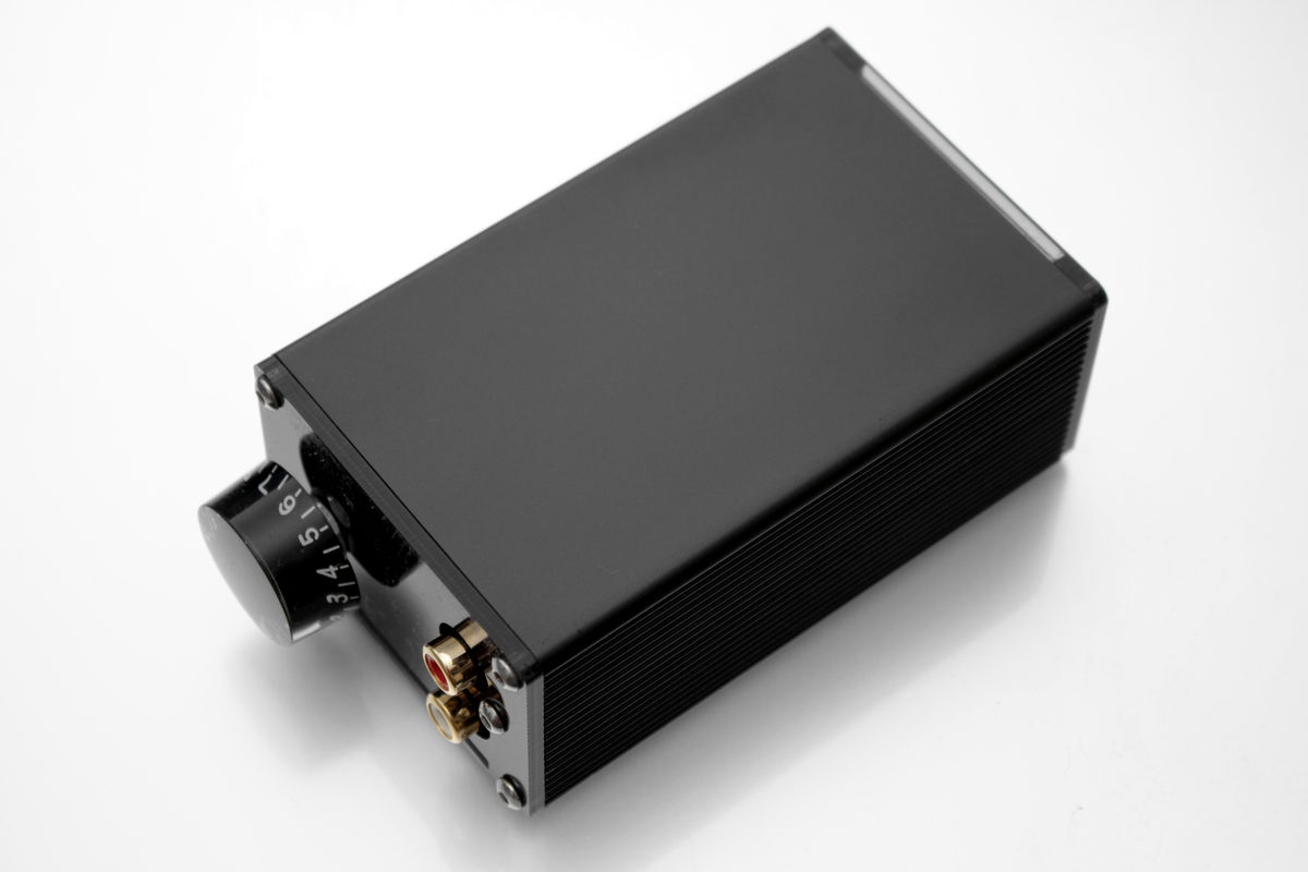
Finally managed to get my case done. 🙂
TPA3251 (TPA3255) aka ?Model Tiny? in Aluminiumgehäuse ? #360customs
TPA3251 "Model Tiny":


Hope to get the revision done on the blue board soon to order some new boards. (Finally for the DIYers)
TPA3251 (TPA3255) aka ?Model Tiny? in Aluminiumgehäuse ? #360customs
TPA3251 "Model Tiny":
Hope to get the revision done on the blue board soon to order some new boards. (Finally for the DIYers)
Nice, Doctormord!
I'm curious about the thermal bridge. I've seen the photos on your site, but I'm not clear on a few things. Is there just one? Is it affixed to the case, or the board/chip? Is there just one silicone pad? You refer to the plates as "soldered" do you solder them to the top of the chip, or did you build them up be soldering together thinner sheets?
Thanks.
Thanks for the question. The heat bridge consists of 3 copper sheets which are polished first and then soldered together by reflow and solder paste. This then gets connected to the case by the thin thermal pad as the case isn't that flat due to the manufacturing process of extruding. The thermal connection between the 3251's thermal pad and the heat bridge is just "press fit" without any grease as the thin top copper sheet is rather soft.
Doing so, the heat bridge sits straight and tight on the 3251's top pad with minimal thermal resistance, any non-flatness is carried out by the thermal pad.
The solution is able to handle 100Wrms (or 2x50Wrms) continuous output power at 30°C ambient. Thermal flow is quite good as the case is heating up quickly to about 60°C. With an efficiency of 90% there's 10W thermal loss at 100W output power, so the solution is at ~3K/W. When listening to music higher output power isn't a problem due to "burst"/crest factor.
The only limiting factor then is the inductors saturation current limit at ~8A.
Last edited:
doctoemord are you selling the small boards or just the larger boards to diy'ers. I would love to get a pair of boards to go with some prototype work I am doing. It will be one part of a development project using the ADAU1701 chip.
Thank you,
Steven
Thank you,
Steven
Hi, I stumbled across a video of TI explaining how their Class D amplifier works by using TPA3251d2 as example. I'm sorry if this has been shared before.
https://www.youtube.com/watch?v=Y9k-waQ6evY
https://www.youtube.com/watch?v=Y9k-waQ6evY
interesting reading on how to add Post Filter Feed Back to TPA325x
http://www.ti.com/lit/an/slaa702/slaa702.pdf
http://www.ti.com/lit/an/slaa702/slaa702.pdf
Now this is interesting - post filter feedback would greatly improve the load impedance sensitivity of the amp, which IMO is the biggest issue with these pre-filter-feedback class D chips.interesting reading on how to add Post Filter Feed Back to TPA325x
http://www.ti.com/lit/an/slaa702/slaa702.pdf
Once I get the Wiener build done, I've got some experimentin' to do...
Has there been any new thread about doctormord's PCBs in vendor section or the interest to use TPA3251 has naturally vanished?
True true. Not everyone has a warm summer now 🙂It's summer out there, everyone's outside i guess. 🙂
How easy would it be to provide a balanced signal to this chip? Would one still need the input buffer stage? Or I should say preamp stage if there is any gain required.
The actual board is SE only, the revised will be SE/Diff with gain. (or Diff bypass)
I genuinely respect your work but my question was more generic as I believe this thread is about any implementation of the chip. If I read the datasheet correctly the chip requires pretty high input voltage which is exactly opposite to what I would intend to use it for (i.e. taking signal directly from a balanced DAC chip). I just fear that the opamps used for the gain can bring their own sound signature.
I think it is very hard to understand drMords enterprise startegy. Is it a private project, does he aim for sales, for fame and admiration?
//
//
I genuinely respect your work but my question was more generic as I believe this thread is about any implementation of the chip. If I read the datasheet correctly the chip requires pretty high input voltage which is exactly opposite to what I would intend to use it for (i.e. taking signal directly from a balanced DAC chip). I just fear that the opamps used for the gain can bring their own sound signature.
True, the inputs "need" ~2.45Vrms for full output. A 3Vrms DAC output should do.
@TNT, this is a private project made in my spare time. I'm still studying. So, no enterprise strategy. 🙂 From time to time, things get finished.
Last edited:
- Home
- Amplifiers
- Class D
- TPA3251d2