Hell yes, TPA3250D2 just popped up on the TI website. No samples or anything yet, but based on the product sheet, looks like a TPA3251D2 with the thermal pad facing down.
Hurry up and sample this, TI 🙂
Yes I noticed that too. 😀
Hell yes, TPA3250D2 just popped up on the TI website. No samples or anything yet, but based on the product sheet, looks like a TPA3251D2 with the thermal pad facing down.
Hurry up and sample this, TI 🙂
>100W out: >10W heat into the PCB.
No thanks
>100W out: >10W heat into the PCB.
No thanks
Yes with continuous operation, but music typically has a 10dB crest factor, so even at full power you're only going to be dumping 1W into the PCB. This is not a major concern and is much more suitable for applications where one doesn't need the extra power and requires a smaller form factor. Plus not having to engineer in the mechanical for the heat sink is a huge bonus towards complexity + not having to worry about parts clearance between the board and the heat sink.
Yes with continuous operation, but music typically has a 10dB crest factor, so even at full power you're only going to be dumping 1W into the PCB. This is not a major concern and is much more suitable for applications where one doesn't need the extra power and requires a smaller form factor. Plus not having to engineer in the mechanical for the heat sink is a huge bonus towards complexity + not having to worry about parts clearance between the board and the heat sink.
There is that side of it.
What 5th E. said. I'm not making amps for listening to full scale tones.
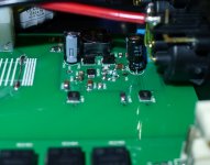
I've been stuck on the heatsink design on my amp, there isn't really anything off the shelf that fits my card design well and doesn't require machining. Plus having no top side heatsink means I can do very good decoupling.
Sent from my Nexus 4 using Tapatalk
I've been stuck on the heatsink design on my amp, there isn't really anything off the shelf that fits my card design well and doesn't require machining. Plus having no top side heatsink means I can do very good decoupling.
Sent from my Nexus 4 using Tapatalk
Yeah I really don't know why TI didn't choose a slightly thicker package to increase clearance to the heatsink. It always amazes me at the number of times when a manufacturer goes with a tiny format IC and you either need to couple it with gigantic supporting components or whack a huge heatsink on top of it. As if making it 50% bigger would do anything to realistically increase the PCB area requirement for the system, yet make it a lot easier to work with on a number of levels.
Still I went with this.
Copper Flat Bar C106(Soft)10,20,30,40,50,100mm x4mm Available in various lengths | eBay
Copper bar.
I cut out a little square of copper to sit between the thermal pad on the 3251 and the heatsink above, giving me extra clearance to work with. Granted this wont have quite the thermal performance of mating a sink directly to the top of the chip, but in my application it is not needed and the clearance is!
I guess I feel that I design at a level of what it could do. (I agree that is not how I would use it.)
I would also like to test them at full power and I don't have burst waveform generation capability.
But I do understand your position...I will stick with the TPA3251d2.
I am interested in seeing the board layout.
I would also like to test them at full power and I don't have burst waveform generation capability.
But I do understand your position...I will stick with the TPA3251d2.
I am interested in seeing the board layout.
Copper bar...I used something similar to get the heat to the sink for a TDA8954.
(Yet to be built)
(Yet to be built)
Anyone scanned through the EVM manual already?
http://www.ti.com/lit/ug/slvuam9/slvuam9.pdf

Source: http://www.ti.com/tool/tpa3250d2evm
http://www.ti.com/lit/ug/slvuam9/slvuam9.pdf
Source: http://www.ti.com/tool/tpa3250d2evm
Attachments
Hey hey, good find. Creating the part now, gonna have the PCB/parts ready for when the chip drops.

It's a shame TI made the TPA3250D2 NOT pin-compatible to the TPA3251D2. 
(Bolted the die "upside down" into the package.. 😀 )
While the outputs are not affected - just swapped, the inputs/controls are now on the opposite side of the pin strip.
"Fun fact", those TPA3251D2 and TPA3250D2 seem to be "reused" PWM motor drivers aka DRV8432 with additionally internal analog frontend.
Just have a look into the datasheet:
http://www.ti.com.cn/cn/lit/ds/symlink/drv8432.pdf
Last edited:
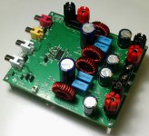
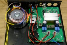
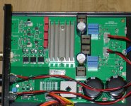
After some delay my amp
Hi,
Just a short notice for people considering this chip for an amp.
I finished designing and building this amp.
Before this I designed class-A amps... 🙂
The sound of this chip turns out to be very good. It sounds like a class-AB amp. I compared with the eval board of the TAS5630b and the TPA3251 sounds much better (but has less power).
I also compared with the IRS-2092 ref design iraudamp7s. This is a much closer contest where the iraudamp7s offers more detailed sound but sounds a bit bright on some music. The IRS-2092 has noticeable more background noise compared to the TPA3251.
When cost / size / power use is not a factor, I still prefer class-A amps, but this chip comes close and does not have the typical 'class-d sound' of earlier single chip solutions.
Attachments
Last edited:
Nice work! Thanks for the listening report.
I still haven't finished my PCB layout as have been waylaid by other projects over Xmas. Will post when done.
I still haven't finished my PCB layout as have been waylaid by other projects over Xmas. Will post when done.
What is this switcher you used? Symmetric output for the analog front-end?
The front end power is from TI design "slva369a split rail supply with TPS54160". I changed the output voltage to +/-15V (R1 = 36.5k) to have enough voltage drop to use common 7812/7912 regulators as the now often used low dropout LM2940 / LM2990 are expensive, have high noise and the ripple rejection at high frequencies is not better than cheap 7x12 regs.
As the load on the switching regulator is asymmetrical (100mA from +, 20 mA from -), the output voltage is +14.8V / -15.2V, post regulators are needed to get a symmetrical supply. To get +12V for the chip amp, I use a separate 12V reg.
The 7812/7912 have only about -20dB ripple rejection at 1 MHz, so I added a 10uH inductor before them to get rid of the HF ripple from the switcher.
Rob
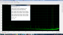
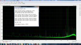
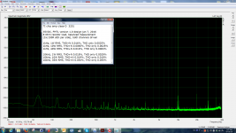
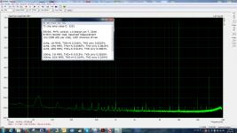
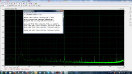
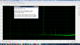
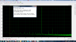
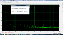
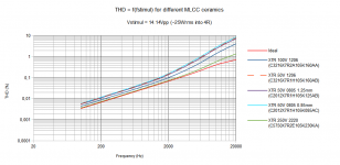
The objective side: measurements
Measurement done with Arta 1.8.2 and a Julia sound card in ASIO mode, using a balanced attenuator (2x 1k/150ohm) and the balanced inputs of the sound card. Sample freq was 96k so can see till 48k. PrismSound passive low pass filter was used to avoid interference with the class-D carrier signal.
Some observations:
1) At 1 kHz, the THD performance is very good. At lower powers, the spectrum is totally clear. Very good for a class-D.
2) At 10kHz, the distortion is higher, but lower than most class-D and also marginally lower than the IRS-2092 reference. However, a good modern class-AB does this better.
3) IMD 18k+20k looks very good for a class-D amp. Only at levels above 10W, the spectrum becomes a bit crowded. Also here the performance is a bit better than the IRS.
During test the heat sink was not very warm (<50 C)
Conclusion: better than I expected, the TPA3251d2 is a large step forwards in single chip class-D amps.
Hopefully useful.
Rob
Cyenne Audio
Attachments
-
 Screenshot 2016-01-07 20.55.51.png204.6 KB · Views: 134
 -
 Screenshot 2016-01-07 20.54.53.png203.2 KB · Views: 139
 -
 Screenshot 2016-01-07 20.52.00.png204.3 KB · Views: 145
 -
 Screenshot 2016-01-07 20.37.45.png201.1 KB · Views: 123
 -
 Screenshot 2016-01-07 20.36.06.png198.5 KB · Views: 134
 -
 Screenshot 2016-01-07 20.33.11.png196.1 KB · Views: 146
 -
 Screenshot 2016-01-07 20.24.40.png190.7 KB · Views: 175
 -
 Screenshot 2016-01-07 20.22.53.png188.7 KB · Views: 189
 -
 Screenshot 2016-01-07 20.21.20.png185.7 KB · Views: 394
Hi Rob,
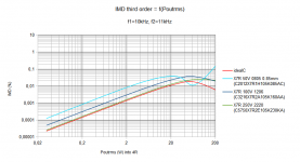
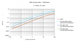
thanks for the input. I'd be interested to see the IMD with another inductor, as they have a quite "high" impact on performance.
From a simulation:
And may i ask for a measurement with MKT/MKS at the output, compared to the now used MKP?
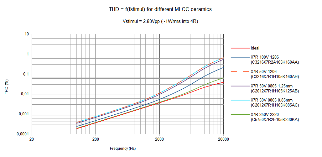
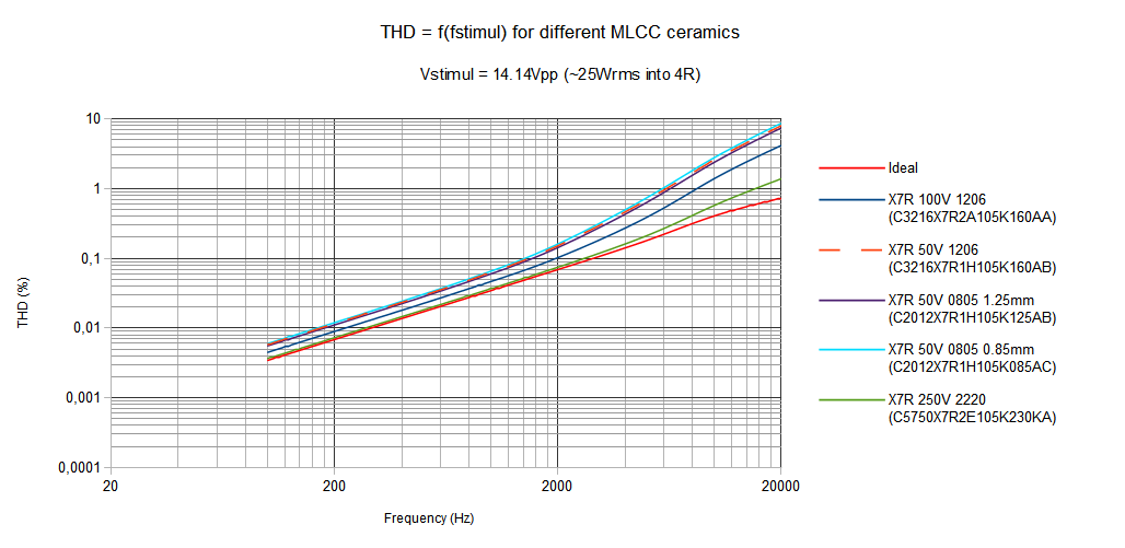
Im still a bit unsure, if MKT/MKS would to the job in my shrinked down version of this amp. I did some simulations regarding this (THD, IMD) for MKP as the "idealC" compared to "oversized" ceramics" like shown.
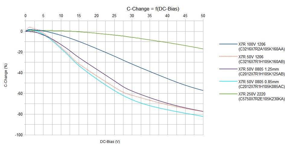
The simulation is done with the TDK dc-bias modells which also includes C=f(f).
DC-Bias:
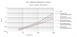
THD = f(Pout):
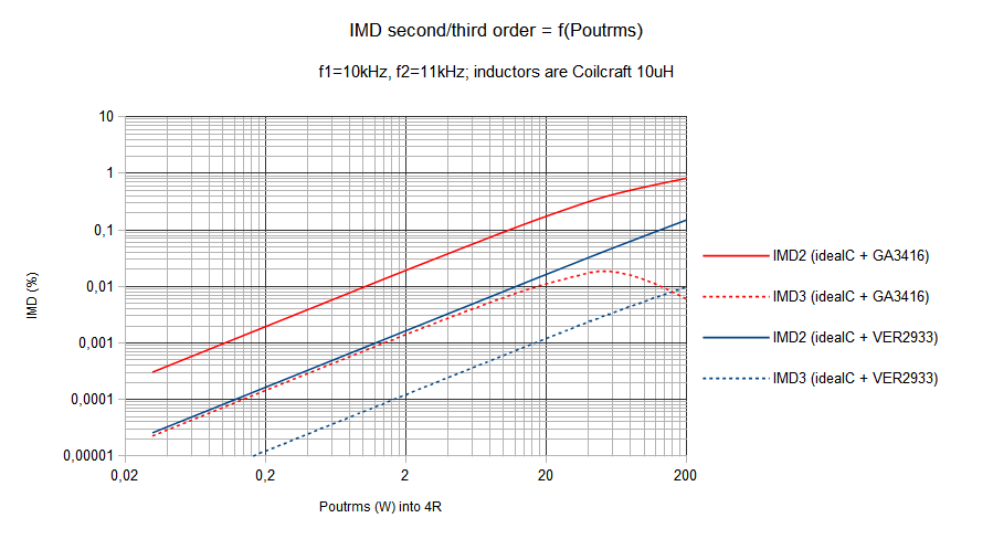
IMD for different caps:
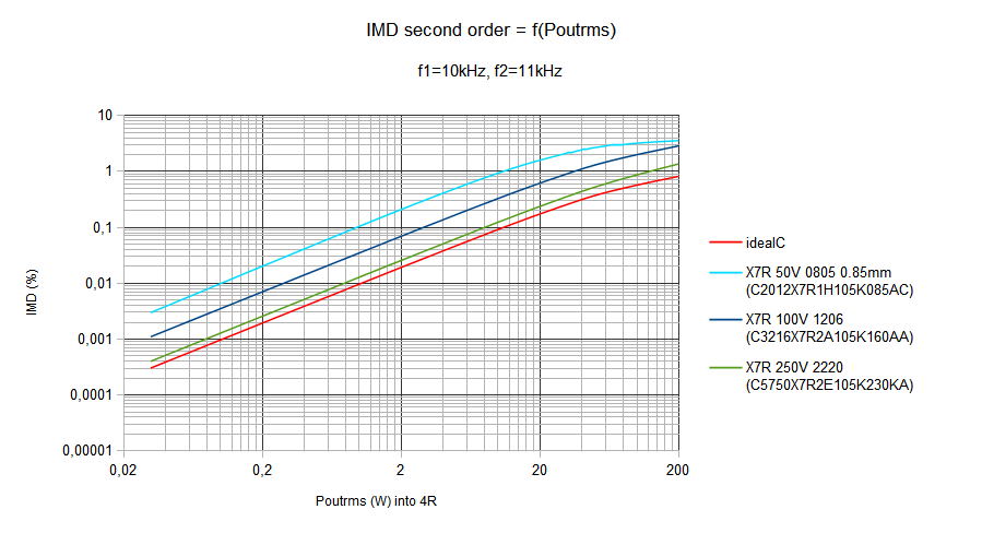
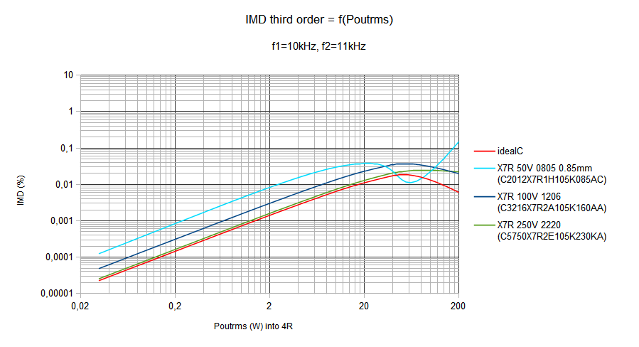
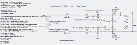
The simulation is done on this setup:
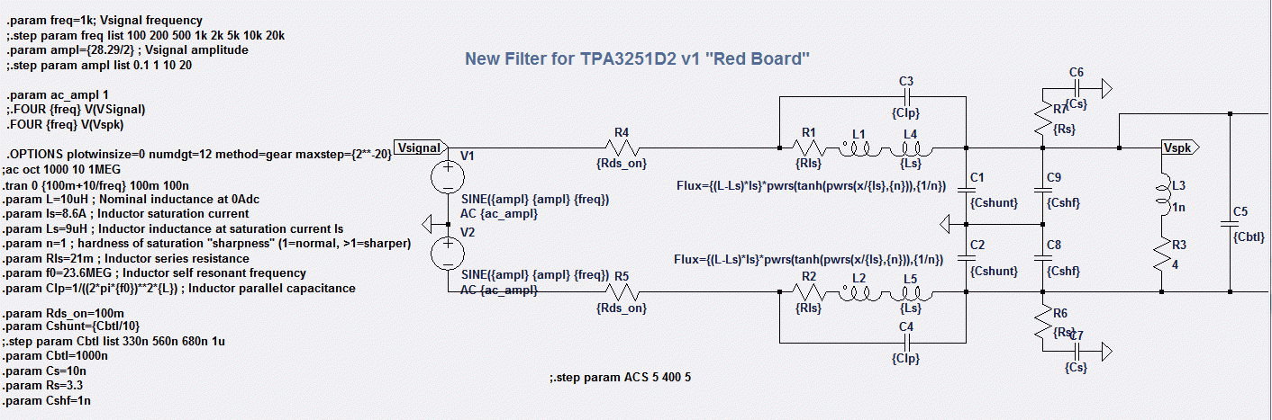
All simulations are down with the parameters of Coilcrafts GA3416 (except otherwise noted), so the charts are biased with those characterics and the math behind the inductor-modell.
Regards,
Christian
thanks for the input. I'd be interested to see the IMD with another inductor, as they have a quite "high" impact on performance.
From a simulation:
And may i ask for a measurement with MKT/MKS at the output, compared to the now used MKP?
Im still a bit unsure, if MKT/MKS would to the job in my shrinked down version of this amp. I did some simulations regarding this (THD, IMD) for MKP as the "idealC" compared to "oversized" ceramics" like shown.
The simulation is done with the TDK dc-bias modells which also includes C=f(f).
DC-Bias:
THD = f(Pout):
IMD for different caps:
The simulation is done on this setup:
All simulations are down with the parameters of Coilcrafts GA3416 (except otherwise noted), so the charts are biased with those characterics and the math behind the inductor-modell.
Regards,
Christian
Attachments
-
 Comparsion_14.14V_approx_25Wrms_into_4R.png39.6 KB · Views: 1,002
 -
 Comparsion_2.83V_approx_1Wrms_into_4R.png40.5 KB · Views: 989
 -
 DC-Bias.png43.3 KB · Views: 1,013
 -
 IMD_3nd_order.png33.6 KB · Views: 986
 -
 IMD_2nd_order.png32.8 KB · Views: 995
 -
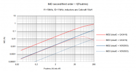 IMD_23nd_order_inductors.png32.1 KB · Views: 1,011
 -
 filter_snipped.png99.7 KB · Views: 994
Last edited:
- Home
- Amplifiers
- Class D
- TPA3251d2