Hi Christian,
Nice research!
For the output inductor on a good class-d amp, I've found it needs to be oversized and especially designed for high quality class-d audio to avoid it from dominating the distortion figure in both 10k THD and IMD. The dual Coilcraft you mentioned looks a bit small for this amp.
I don't know enough about inductors to verify if your distortion simulation model is predicting real life. You can try to input the 1D17A parameters and compare the results with my measurements. I can measure 10k/11k IMD if you want.
I do know many class-d output inductors are designed for low-end applications to use with chip amps that have 1% distortion anyway, so avoiding distortion while designing those inductors was not priority.
There are only a few inductors really designed for high quality class-d audio. I use good class-d reference designs as a guide to select inductors. Most probably those designers are smarter than me...
In my amp (35V powered, loaded with 8 ohms), the difference in distortion between the Coilcraft from the TI reference design and the ICE 1D17A was lower than the measurement variation of my measurement system. As I can buy the ICE cheaper, I used that one. The saturation current of a 10uH 1D17A is about the same as the 10uH VER2933 you mentioned.
MKT/MKS: their distortion will be still more or less OK compared to the inductor (many AB amps use them in output zobel networks), but their problem for high power class-D is their relative poor dissipation factor which makes them heat up and possibly fail. The TPA3251 runs at 500 kHz... A solution would be to use a much higher voltage rating (like 400VDC) but then they become quite big as well.
For ceramic caps, I try to avoid anything other than NP0 in analogue signal chains. Even for the snubbers/zobels I used NP0 caps. The voltage coefficient of X7R will cause distortion and the voltage coefficient is different from brand to brand, often poorly documented, making it hard to predict the performance of the final product. Of course for power supply decoupling etc. i do use X7R.
Hopefully useful.
Rob
Last edited:
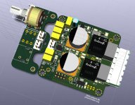
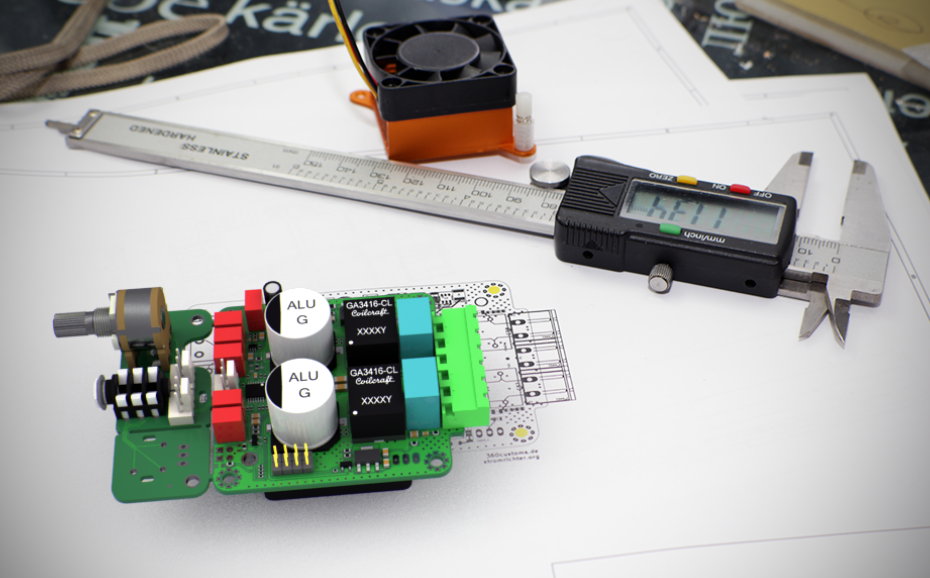
Well, the GA3416 are of course a bit "undersized" but from they can be pushed hard up to 8A very lineary due to their hard saturation. In theory that belongs to 256Wpk into 4R or 127Wrms. I have to say, that this board is 60x60mm only, so space is limited. 🙂
If we look on THD/IMD in theory, that's a totally different story in practice if you take energy density into account. Having i.e. 100W in bass normally isn't correlated to 100W in the highs at the same time. And listening to plain 100W HF is something you normally wont do frequently. So taking normal music program material would result in "virtually less" THD. -> Crest-factor 6-8dB
But yeah, these boards (60x60mm) are meant for boombox/PA. Would guess, they wont perform any worse than the big boards at moderate levels.
For the BC-bias, yes, this is always some kinda roulette but Murata and TDK offer good documentation and even SPICE-models.
Last edited:
Idea for X7R caps
If you really want to use X7R's in the output, maybe the distortion can be controlled by using 2 of the same caps of half of the needed capacity. Connect one to the ground and the other one to the power.
Now the capacity change as function of the music will partly cancel. I did not try this but saw something similar being used in single supply SE class-d amps with the series aluminum capacitor to reduce distortion.
This works perfect assuming the capacitance decreases linearly over voltage - which is not guaranteed at all. Anyway I would expect some grade of distortion cancellation.
On the other hand splitting these caps can serve the additional purpose of blocking the supply rails.
What is the value needed ?
PPS cap ? http://eu.mouser.com/WIMA/Passive-C...rs/SMD-PPS-Series/_/N-9x371?P=1yzojenZ1z0zldh
Like a lot also the Wima MKS4 in 2.5 mm pitch if value below 1 uF... MKT !
PPS cap ? http://eu.mouser.com/WIMA/Passive-C...rs/SMD-PPS-Series/_/N-9x371?P=1yzojenZ1z0zldh
Like a lot also the Wima MKS4 in 2.5 mm pitch if value below 1 uF... MKT !
Last edited:
Work in progress, the "shrink mod".
Baseboard will be 60*60mm to fit in an enclosure, front panel will be an optional brake-away.
when will it be ready for final production ha ha
I'll send the production data to the fab in week 05 i guess. Fitted those bulky MKP, finally. 😀
Attachments
Last edited:


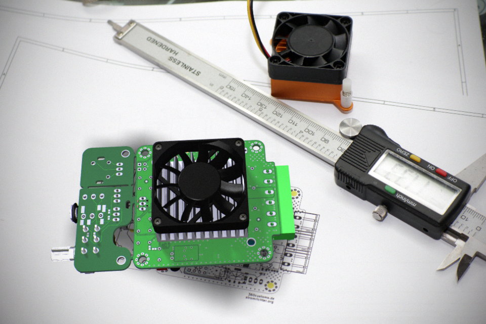
Incredible! Is that an Optical-In socket on the breakaway next to the volume pot? Is a thermo fan controller onboard too?
Its a tight and right looking design with very high quality components. It should spec out very quiet. I like the orientation of the TPA3250 mounted that way, rotated 90 degrees from most other designs.
Mighty fine job Doctormord! Thanks for sharing with us.
Its a tight and right looking design with very high quality components. It should spec out very quiet. I like the orientation of the TPA3250 mounted that way, rotated 90 degrees from most other designs.
Mighty fine job Doctormord! Thanks for sharing with us.
No optical in this time - fan has 2-stage control (low/high).
Actually it's TPA3251D2, TPA3250D2 wouldn't need heatsink (or wouldn't benefit much from it).
Board should run fanless (with heatsink) in normal conditions, needs to be tested.
Actually the IC is directly under the heatsink, mounted "normal".
Actually it's TPA3251D2, TPA3250D2 wouldn't need heatsink (or wouldn't benefit much from it).
Board should run fanless (with heatsink) in normal conditions, needs to be tested.
I like the orientation of the TPA3250 mounted that way, rotated 90 degrees from most other designs.
Actually the IC is directly under the heatsink, mounted "normal".
Ahh.... Still 'out of the box thinking'. Solves the need for a handmade heatsink while keeping the layout compact and tight. Very nice, no compromises, problem solving design. Its obvious that you have put a lot of time and effort into it. I expect it to be an exceptional performer, as I am sure you do too! Thanks again for sharing.
Got the heatsinks today, needed to alter the footprint and board a bit.
So finally, this is it.
Nice!
Yes, very nice design indeed.
So what's the endgame here?
Is this just a personal project, or are boards and/or kits going to be offered for sale?
If the latter, what's the projected pricing?
So what's the endgame here?
Is this just a personal project, or are boards and/or kits going to be offered for sale?
If the latter, what's the projected pricing?
Would say, I will build another small batch 5-10 with this layout, test and characterize them and finally start a group buy maybe or build em just on demand. Alternatively I'll just make the bare pcb available together with a mouser basket for those who want to solder on their own.
Would say, I will build another small batch 5-10 with this layout, test and characterize them and finally start a group buy maybe or build em just on demand. Alternatively I'll just make the bare pcb available together with a mouser basket for those who want to solder on their own.
Hi doctormod,
Firstly, I would like to sincerly send you many many thanks for your talents, skills, and help to the DIYaudio communauty,... We really need people like you and other here on this thread.
to be honest, I really don't like the idea of a fan.
I can ear a little fan in my room, this is why all my digital system from processor to speakers is fanless... Imagine you are listening piano, and suddently the sound stops and you always ear the fan... Of course, when the fan is new it is like the sound of silence.... But after few months, this is another music....
Do you plan to start a group buy for a batch without a fan?
Last edited:
I'll evaluate up to which power-levels the fan is not needed. As the implementation is shrinked down, at high output levels the fan will be needed to keep the system running.
At the "old/first" board (100*100mm) with its bulky heatsink, no fan is needed even at full sinewave output.
5thelement showed in the past that at moderate levels there is no need for a heatsink either. So, at levels below (would guess) 20-30W, no heatsink or fan is needed.
But you have to keep in mind, in small enclosures only passive cooling (convection) wont be enough, no matter what heatsink is used. Peak-power sinks into thermal capacity.
You're free to implement a different cooling, i.e. heat-bridge to case or something similar. I keeped this in mind when i designed the board - so when mounting this board into an metall case, you can have a pressfit-heat-bridge to the case without a fan. The board has 1.5mm space on the sides to slide in the usual chinese aluminum cases.
Alternatively you can glue (thermal-glue) metall of your choice to the IC. 🙂
More choices, more better!
Yep, its a versatile, well thought out and well laid out design. There will be very few environments where you couldn't adapt your amp to perform successfully. You have 'designed in' the necessary options to cover most any execution. Its a very high quality design as well.
I have planned to build heatsinks myself from copper by machining (a raised flat section) from round bar stock, slotting them in radial fashion, then press fitting sections cut from copper sheeting into the slots and tacking in place with solder at each slot end. By making my own copper sinks, plenty of clearance could be provided under the sink for a very tight design. But I appreciate your work more since you have not only solved the tiny chip problem, but in doing so have provided many other options for the end user for mounting and cooling the amp. More choices= More better!

Count me in for a couple bare PCBs when you are comfortable with it.
-Mark
Yep, its a versatile, well thought out and well laid out design. There will be very few environments where you couldn't adapt your amp to perform successfully. You have 'designed in' the necessary options to cover most any execution. Its a very high quality design as well.
I have planned to build heatsinks myself from copper by machining (a raised flat section) from round bar stock, slotting them in radial fashion, then press fitting sections cut from copper sheeting into the slots and tacking in place with solder at each slot end. By making my own copper sinks, plenty of clearance could be provided under the sink for a very tight design. But I appreciate your work more since you have not only solved the tiny chip problem, but in doing so have provided many other options for the end user for mounting and cooling the amp. More choices= More better!
Count me in for a couple bare PCBs when you are comfortable with it.
-Mark

- Home
- Amplifiers
- Class D
- TPA3251d2