specd, I've started a 3251 design in kicad and I'd be happy share footprints or any tips needed. My board will have dual 3251s so likely the PCB won't be easily shareable but I'll post it to GitHub if you want.
Thats great deanbob! I figured out the footprints tonight so I'm good to go for a while. But I'd like to follow along with whatever you want to share!
My plan was also a two-chip board, dual PBTL, for subwoofers. I may back down from there and make them single chip boards if I feel like its getting over my head. Power might be an issue too....
I like the small board Doctormord is working on and a single chip may be smarter for me... for my first experience. The chips are all shipped (five-3116s & two-3251s) but I gotta take my time on this and learn as I go.
Still thinking about boost power supplies since I'll be running the amps off solar power/lead-acid battery bank. I have a couple of them but gotta upsize. Only when the sun shines... 😀
Thanks again, much appreciated!
Sure. Reading this thread from the start will help, lots of knowledgeable folks here willing to help/share. If this is your first experience better to try with a simple design - I suggest using the evaluation board schematic and layout as it is the recommended setup by TI. And don't forget to read the entire datasheet as well!
Yep, great advice, particularly for a newbie like me! I am thinking along the same lines as you for my first board... Planning on sticking as close to EVM designs as possible, as its safer. I have read this entire thread and most of the 3116 thread as well. And of course the datasheets and EVM pdfs for both of those chips. TI E2e discussions are very useful too!
Without you folks sharing, critiquing and discussing such a broad range of technical ideas here I couldn't begin. I especially like the critiquing type discussions, no one gets personal and progress is always made! Awesome resource!
Today I woke up a bit less gung ho... thinking more conservatively.... I spent a lot of time and money getting to this point and still feeling quite dumb... so I am thinking about making a 3116 board first, because its simpler looking. Kicad hasn't been easy and I need experience.
I intend to do a couple 3251 boards but I have all winter, so I am going to soak up these threads and work on my skills.
Thanks!!!
If you need special help on KiCAD where you can't find a solution elsewhere, let me know. 🙂
Let me say, it's best to make yourself your own library to not rely on footprints not made by yourself or to your demands. Sources are data sheets and i.e. "LP Calculator".
https://blog.adafruit.com/2009/11/16/lp-calculator/
Let me say, it's best to make yourself your own library to not rely on footprints not made by yourself or to your demands. Sources are data sheets and i.e. "LP Calculator".
https://blog.adafruit.com/2009/11/16/lp-calculator/
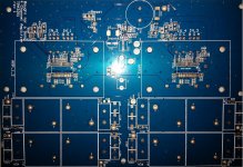
Been following this thread! Great information and posts, thanks for taking the time everyone. Attached is a pic of my board. Hope to have it running soon. Decided to go straight to 4 speaker channels per board.
Bulk capacitors are installed on the bottom of the board to move them a bit closer to the pins. 0402 will fit under the heatsinks. Looking forward to listening to them. Currently running the TPA3116 and these sound good. Pretty much TI reference design with LT8614IUDC#PBF switcher, a few more caps and Silmic bulks. Was on a budget so footprints are for 1D23A-100M ICE components, PP and PET caps for output filter.
Boards were manufactured by PCBway. I've gotten a number of designs done by them and all have been acceptable quality and on-time.
Looking forward to reading more subjective reports!!
Attachments
What drill size are your output connecting vias? Those look a bit small to me on the picture. Not tenting them would also increase thermal performance at this point as the resistance increases with temperature/current flow.
Hi Doc,
You are correct, holes are only 18mil (had trouble fitting larger ones in there) also should have cleared the mask between the output pins and maybe a few PWR and GND pins too. Probably not enough to force a rev at this point. When hand soldering I've had trouble with pin shorting when I've done that (shaky hands!) so I wanted to keep it cleaner this round. Looking forward to getting these on some drivers. I like the chips distortion graphs but I probably won't be able to hear a difference.
You are correct, holes are only 18mil (had trouble fitting larger ones in there) also should have cleared the mask between the output pins and maybe a few PWR and GND pins too. Probably not enough to force a rev at this point. When hand soldering I've had trouble with pin shorting when I've done that (shaky hands!) so I wanted to keep it cleaner this round. Looking forward to getting these on some drivers. I like the chips distortion graphs but I probably won't be able to hear a difference.
Thanks Doctormord! Yep, I don't trust public footprints either, thats why I decided to make them myself from TI package specs. KICAD is great on Linux, its me that gotta get with it.
Thanks for sharing your design Mikealanlee, thats real tight! 0402s fit nicely there. Great job!
Thanks for sharing your design Mikealanlee, thats real tight! 0402s fit nicely there. Great job!
Last edited:
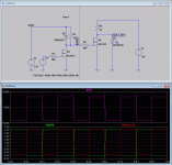
U3 is LT8614IUDC#PBF and since I'm hand soldering, snip though holes close and don't use too much solder 😉!
Thanks all, will post schematic later today but please go easy on me as I didn't draw the schematic for public consumption. Also the LED driver circuits are not great as I wanted to use less parts 🙂. Opps, looks like I forgot the pullup resistors on the fault and clip lines 🙁.
Thanks all, will post schematic later today but please go easy on me as I didn't draw the schematic for public consumption. Also the LED driver circuits are not great as I wanted to use less parts 🙂. Opps, looks like I forgot the pullup resistors on the fault and clip lines 🙁.
Last edited:
Would be interesting to see how good the switcher performs, (to me) layout can be improved at this point. At what frequency do you run that thing?
Everything could be better but the layout is pretty close to the datasheet. This footprint is very hard to work with. If you take a look at the recommended layout via datasheet, even that seems compromised (running power on a different layer while running back to the feedback pins?). Getting space for the internal vias requires some reducing of the annular rings that I normally wouldn't do and I didn't want to reduce the via size for manufacturing/cost. Let the compromising begin! I've used this switcher before so there is reasonable chance of it working (as well as it could for this board). Running it at 1Mhz I believe. Might have to change if it causes problems. Surprisingly, this footprint works quite well for soldering.
Also seemed like a waste to put a power supply on and only running 1 amp so the decision was made to copy another AMP on the board. This caused a few of routing issues. By no means was this meant for perfect end game designed sch and PCB. I think that would a 4 layer taking up more space.
The schematic and PCB were done in less than a working day as I came across this thread just before putting in an order for some other designs (could save shipping!!).
No problems with the layout in common 🙂 I also stumbled over the feedback connection in the reference layout. (the hell?)
My concerns are that the caps won't perform optimal at 1Mhz compared to proper ceramics at this frequency. (But those OS-CON might/will do.) 🙂
Edit:
From the schematic, you also don't use pull-ups at the ~FAULT/CLIP pins like i did in my first layout. Works... 😀
My concerns are that the caps won't perform optimal at 1Mhz compared to proper ceramics at this frequency. (But those OS-CON might/will do.) 🙂
Edit:
From the schematic, you also don't use pull-ups at the ~FAULT/CLIP pins like i did in my first layout. Works... 😀
Last edited:
Hi doc,
Whew! Good to hear the pull-ups are not an absolute. I took a quick look at the amp reference and datasheet again and seemed like they were needed🙂. Would have been horrible to run 2 jumper lines to the divider circuit. I see the chips are finally in-stock where I can order so I'm off to the internet store!!
Whew! Good to hear the pull-ups are not an absolute. I took a quick look at the amp reference and datasheet again and seemed like they were needed🙂. Would have been horrible to run 2 jumper lines to the divider circuit. I see the chips are finally in-stock where I can order so I'm off to the internet store!!
I must correct the above, there are internal pull-ups already (26k).
Beside this you can source some current from the DVDD pin, I.e. if you want to have external pull-ups, as long as current is <9mA to each pin.
Source: TI engineer
Beside this you can source some current from the DVDD pin, I.e. if you want to have external pull-ups, as long as current is <9mA to each pin.
Source: TI engineer
Last edited:
- Home
- Amplifiers
- Class D
- TPA3251d2