Why does this photo look like a render, or is it a render? Dr Mord's renders are so photo realistic I am not sure what I am looking at anymore. 🙂
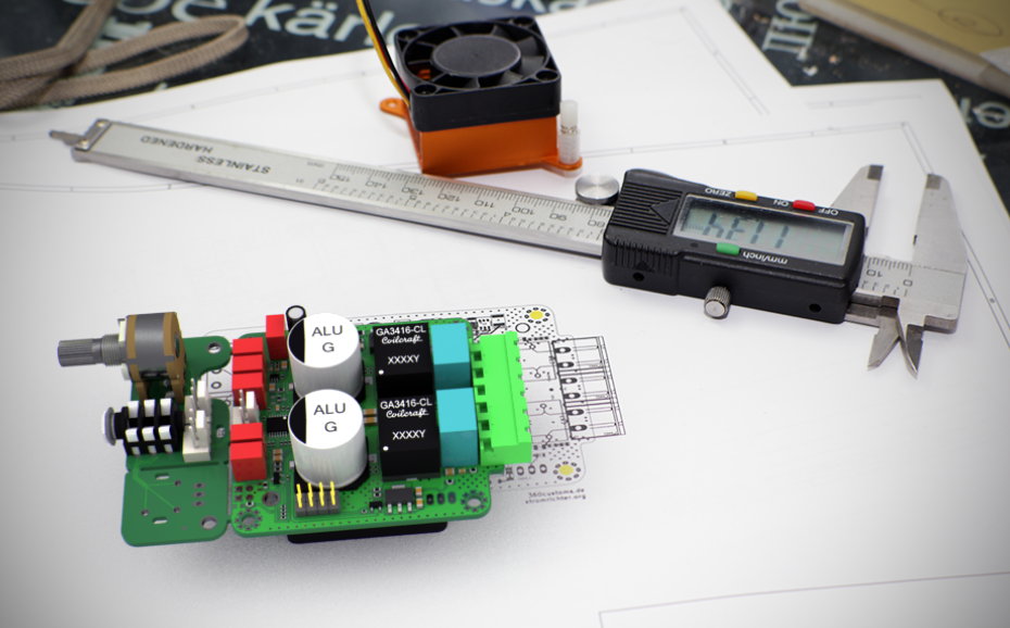
Glad to see I'm not alone in noticing how many issues bottom-mounting the TPA3251 solves 🙂 Though even with that trick, squeezing it down to 6x6 cm is quite the impressive feat, especially with inclusion of all the voltage regulation on board. Quite nicely done.
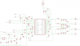
I've been having fun with a slightly different approach given that my aim is multi-channel home theater duty. So size isn't as much of a concern as ensuring that the chip can perform to its peak capabilities, aka larger passive components. (Specifically, the ICE 1D23A inductors and 22.5mm pitch film capacitors on both input and output 1uF spots.) As well, since my intent is for usage in multi-channel I opted for off-board 12V regulation with separate inputs for the VDD and GVDD (could still be tied together of course.) Then for the same reason also included a 12V trigger input in the reset circuit - both allows for putting center/surround modules into reset when just listening to stereo and should ensure reset goes low before there's much of any fluctuation in voltages. Note that I haven't gone through to confirm part values on the schematic just yet, in particular need to get around to actually modeling the reset circuit.
And there's no question that this is entirely too entertaining. Quite unfortunate that I didn't notice how affordable PCB prototyping had become until just this year, haha.
Attachments
Would say, I will build another small batch 5-10 with this layout, test and characterize them and finally start a group buy maybe or build em just on demand. Alternatively I'll just make the bare pcb available together with a mouser basket for those who want to solder on their own.
Great work!
I'm in for 3 boards, either bare or semi-populated (everything mounted except no output filter).
I suspect that the output filter will attract the most debate, so a semi-populated version might be popular?
Cheers,
Mike
Class D Inductors
From what I can find on the 'net there are only two companies providing high current Inductors designed for Class D: Ice Components and Coilcraft.
Ice gets a lot of good reviews from people using them, but there is no hard data published by Ice to prove their worthiness. We get Isat & Idc, a footprint and a low price, thats it.
Coilcraft includes a current saturation graph in their datasheet that reveals a flat line all the way to the advertised saturation point, then drops into steep vertical as you would expect from a quality Inductor. They also list THD+N vs voltage/load distortion limits in the datasheet. Thats relevant data.
For sure, the Coilcraft Inductor appears a bit inadequate. But in most real usage cases the GA3416 should be OK, as most of us won't tolerate listening to an amp thats cranked into distortion and/or clipping and the GA3416 should get close to that range at 4R loading. So it looks like we are stuck with a less than desired Inductor for now. 🙁
I agree with Doctormord's decision on this... Until there is enough data published to base a decision on to use the Ice Inductor, I wouldn't risk having it onboard, potentially wasting my time and money on an otherwise exceptional effort.
Adapting the thru-hole Ice to the Coilcraft pads will be no fun task either, so I'm done worrying about it too.
.... some said the NC Core are just near the UCD technology with a better output filter , was it a myth 😱 ?
I don't remember if the powersupply is embeded in the design of the TPA board ?
I don't remember if the powersupply is embeded in the design of the TPA board ?
There actually aren't any inductors (afaik) which would fit the board at this current rating. I'd chosen those because of the higher "linear" current over the other coilcraft dual inductors which could handle bit more rms current (temp wise).
Maybe a riser board/adapter would fit other inductors. 🙂
But at first I'm interested in how those puppies perform.
Considering 8.6A Isat 10% would theoretically give 147.87Wrms. (Of course not continuous sine wave due to overheating) So 8R will be fine, <=4R needs some thermal derating and burst mode analysis. As those high power output levels are mainly on the low end of audio increased distortion won't be necessarily a problem as the speakers do distort way more than the output filter.
Eldam, what supply are you referring to? You just plug in your power supply (min 16V, max 36V) and you're all set.
Last edited:
HI Dr Mord,
Thanks for your answer,
I am very confident with your design and the chip as well.
You talk about current ratting, what is the max current capibility in which the amp is in a confortable zone without distors ? 8 A if I understood !
In fact I'm interrested by multi amplification for an active speaker, but this pretty thing seems good enough even for a multi-ways passive speaker 😎!
Did you abstract the limit of its possibility to drive a passive seaker with not gentle filter ? For instance : 3 ohm deep or less in the impedance curve of the speaker ?
When you talk of Power supply, do you talk of AC or DC, just the secondary in the ratting you gived and that's ok ? Is there a VA advised ?
I'm looking forward to have your first listening impressions 🙂
Last edited:
36Vdc is the optimum.
Talking about the current limit, this is given by the inductors at different points. 8.6Apk is at 10% drop of inductance. Pushing harder results in more drop. At the saturation point inductance drop is modulated by audio current, so filter frequency (-3dB point) is modulated as well which results in distortion from the filter. As this IC is pre-filter-feedback this won't be corrected. Another aspect to keep in mind is the minimal inductance the amp protection needs to have to work properly.
And all this(except protection) is a function of time. With music signal at a crest factor of 8:1 there won't be any trouble even at full power and 4R load.
2R loads should do fine in PBTL configuration.
Thank you a lot for all these datas 🙂
PBLT ? What is it ? I assume it is not "Pork Baccon Lettuce & Tomatoes" ?!
@ DIYAUDIO members,
Any cheap swittching PS of shelves free of EMC enough, with 36 Vdc output and enough A. ? What did you plan to feed this good board ?
PBLT
? What is it ? I assume it is not "Pork Baccon Lettuce & Tomatoes" ?! @ DIYAUDIO members,
Any cheap swittching PS of shelves free of EMC enough, with 36 Vdc output and enough A. ? What did you plan to feed this good board ?
Last edited:
SLA or LiIon with boost-converter. 😀
At home i use an LLC power supply (230V -> 36V) made by @voltwide.
At home i use an LLC power supply (230V -> 36V) made by @voltwide.
Attachments

Last edited:
Ice gets a lot of good reviews from people using them, but there is no hard data published by Ice to prove their worthiness. We get Isat & Idc, a footprint and a low price, thats it.
From the measurements that I've made using the Ice inductors they would appear to give you performance akin the performance outlined in the TI data sheet for the TPA3251D2.
Certainly going with their bigger inductors would guarantee low distortion at high power levels but all my measurements with their smallest model would indicate that they are quite capable. The spec sheet also indicates that they should be fine for the power levels that the 3251 puts out and especially so for the 3250.
And always way better than the Coilcraft MSS series. This might be a construction issue. (As i remember we both tested the MSS1278 size)
SLA or LiIon with boost-converter. 😀
At home i use an LLC power supply (230V -> 36V) made by @voltwide.
I was sure it was not about Lettuce & tomatoes !😀
I saw there are cheap LiPoFe4 12V battery for motorbike now : huge currrent capabilities and long life recharching cycles (> 2000 loads) !
The esr is even lower thean LiPo if I don't make a mistake (?) : 3 in serie (=36V, maybe limit as in real lifze it could be a little more ; 3.4V by element) should have a sota ESR enough at even lower price than LiPo and safer for fire issues in our homes ! Although finding the good supply to load them with cells balancing is not so easy ! But with Google, Nothing impossible in the XXI° century ! 🙂
Thanks for that info 5th Element! I wasn't aware that you had tested the Ice for distortion. Maybe they are a superior Inductor...? If so, its aggravating that Ice don't publish enough data to prove their worthiness. 🙁 Your experience and feedback is valuable, much appreciated!
I am excited about Doctormord's compact 3251. Can't wait to hear how he feels about it after testing! 😀
Doctormord, may I ask which switcher you have in your (voltwide made) power supply? Its a quality build and... I have chinese made boards that I am running off my solar power battery bank and they are too dirty to use on an amp. Do you know of any decent DC-DC boost boards that I could buy?
Thanks,
Mark
For the LLC converter you better ask "voltwide" directly, he's around on the forum here as well. The controller ic is this one:
http://www.onsemi.com/pub_link/Collateral/NCP1396D.PDF
Step-Ups i actually use for this amp with the mobile PA system is either a TL494 based 150W or a modified version of this one:
10/30/50/100W LED application driver (UC3843A) - #360customs
This one is based on UC3843A.
Both are not made for 350W continous output but handle the amp quite well with normal music program.
🙂, thanks ! And I'm not sure how a LiPoFe4 with their huge current instant capability could damage (without sofstart) or not such pcb when switching on the powersupply ?!😕
Ah and I've got it for the P of PBLT ! Parallel...
Readed the datasheet of the 3521-D2 chip... and what BLT is. My noob comprehension is the output in current would be always the same but just the swinging voltage is rising at each bridging : SE to BLT then PBLT .
So 8 A in the 10% DHT as you said for the confort zone and not to low R with complicate passive filter and russian mountain impedance curve with it... even if 2 ohms in PBLT mode !
Protection mode is around 14/15 A if I understood... Saw also the speaker protection mode is only working with the hardware default conf : stereo BLT mode : good to know before playing with speaker wires !
But the SE mode is so atractive for reducing cost with active speaker !
Ah and the SSOT package (didn't see this little detail!) 😀 : is it possible to solder it without air-gun soldering station ? ...
...
Sorry for the extra questions, better for me to wait for a build thread maybe for all the détails or to wait the modalities (bare or populated pcb, number of member in the whiching list, etc).
Anyway : bravo for the design 🙂
Ah and I've got it for the P of PBLT ! Parallel...
Readed the datasheet of the 3521-D2 chip... and what BLT is. My noob comprehension is the output in current would be always the same but just the swinging voltage is rising at each bridging : SE to BLT then PBLT .
So 8 A in the 10% DHT as you said for the confort zone and not to low R with complicate passive filter and russian mountain impedance curve with it... even if 2 ohms in PBLT mode !
Protection mode is around 14/15 A if I understood... Saw also the speaker protection mode is only working with the hardware default conf : stereo BLT mode : good to know before playing with speaker wires !
But the SE mode is so atractive for reducing cost with active speaker !
Ah and the SSOT package (didn't see this little detail!) 😀 : is it possible to solder it without air-gun soldering station ?
...Sorry for the extra questions, better for me to wait for a build thread maybe for all the détails or to wait the modalities (bare or populated pcb, number of member in the whiching list, etc).
Anyway : bravo for the design 🙂
Last edited:
@Eldam,
SE mode is not possible with my implementation, but i don't like SE with single supply due to big coupling caps at the output. When doing SE, a sym. dual supply implementation should be used, like some ICs from ST or IR.
Protection and behaviour is programmable via resistor.
Soldering the SSOT without hot air is possible if you do some praktice before. Youtube is a good source of how-to.
- Home
- Amplifiers
- Class D
- TPA3251d2