cog or npo would be perfect, no rise or drop with voltage, but these values can be very expensive if found
Then you already need doctormords amp 🙂 clean 20 watt for all othersI just built these for my kitchen speakers. Probably cannot take 60w but I will be using 19v SMPS brick and 8R speakers so 25w is probably what is all I will need clean.
X-LS Classic kit
These are a great value.
Output capacitors are 0603, and I've got my suspicion they're X5R's in order to get a 35/50V rating assuming they're 0.68uF. Which means at their operating point, they sure as heck aren't 0.68uF... I've also got my doubts that those output inductors can handle 6+ amps of output current without the L dropping out.
I wouldn't call it "audiophile", but it's probably perfectly OK for PA use or a small toolbox-boombox or whatever.
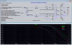
Because of another project i tried the DC-bias cap-modells TDK provide.
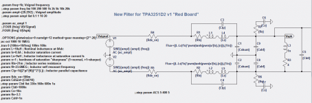
Simulation-setup:
CBTL is substituted with the TDK-capacitor modell. The results were:
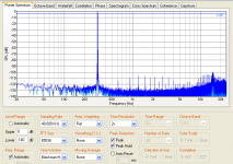
This is for 1kHz.
Using just the "ideal-C" will result in different THD as a function of nominal C-value:
Attachments
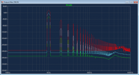
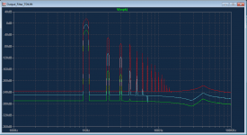
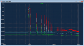
If i'm not completely wrong, the following FFT-plot shows the shift in corner-frequency as a function of dc-bias due to higher input amplitude. Signals are 0.1V (green), 1V (blue), 10V (red). Rload = 4R+47uH.
First, the "ideal C":

Now the 50V X7R 1206 TDK MLCC:

100V X7R 1206 TDK MLCC:

First, the "ideal C":
Now the 50V X7R 1206 TDK MLCC:
100V X7R 1206 TDK MLCC:
Attachments
Last edited:
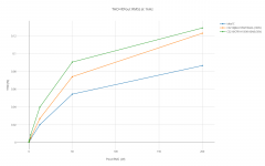
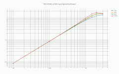
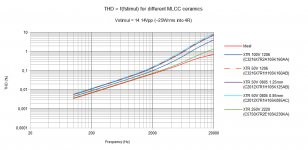
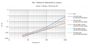
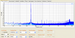
To round this up, here are the results for THD vs. frequency as a function of stimuli-amplitude. Additional THD is introduced by the inductors saturation - so THD performance is to be interpreted relative.
Inductor-parameters are based on "Coilcraft GA3416-CL" with
Lnom=10uH
Isat(10%)=8.6A
Lsat=9uH
Rdc=21mOhm
SRF=23.6Mhz
Test-Circuit:

Capacitance change due to DC-Bias (Data provided by TDK):

At ~1Wrms into 4R resistive load:

At ~25Wrms into 4R resistive load:

Not shown is the impact of speakers self inductance which makes everything more worse. 🙄
Conclusion: MLCC in output filters do work at the expense of increased THD at higher frequencies. Increasing footprint-volume and high-voltage rating helps to decrease THD.
Inductor saturation will additionally rise THD.
Any comments? 🙂
Inductor-parameters are based on "Coilcraft GA3416-CL" with
Lnom=10uH
Isat(10%)=8.6A
Lsat=9uH
Rdc=21mOhm
SRF=23.6Mhz
Test-Circuit:
Capacitance change due to DC-Bias (Data provided by TDK):
At ~1Wrms into 4R resistive load:
At ~25Wrms into 4R resistive load:
Not shown is the impact of speakers self inductance which makes everything more worse. 🙄
Conclusion: MLCC in output filters do work at the expense of increased THD at higher frequencies. Increasing footprint-volume and high-voltage rating helps to decrease THD.
Inductor saturation will additionally rise THD.
Any comments? 🙂
Attachments

Last edited:
For inputfilter formed with ceramics classII distortion rises also towards 20hz, does that also happen in output?
An externally hosted image should be here but it was not working when we last tested it.
For inputfilter formed with ceramics classII distortion rises also towards 20hz, does that also happen in output?
An externally hosted image should be here but it was not working when we last tested it.
Well, input is a different story. We haven't seen that rising THD with the TPA3132D2 board when measured performance but a bit of knock sensitivity.
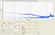
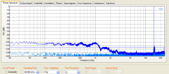
These measurements where done with no load connected to compare the specs with the datasheet.
First with 1uF 25V 0805 No-Name X7R ceramic:
FFT 1kHz:
THD vs. frequency:
Knock sensitivity:
Compare this to a 2u2F 25V 0805 Murata MLCC:
FFT 1kHz:
Knock sensitivity:
Bit better (by ~15dB) below 200Hz (knock sensitivity), the question is, will you hear it? (-90dB) Guess not, the speaker itself is doing more THD at this frequencies.
The situations and input and output are a bit different for the caps regarding to current "pumping".
I'll see if i can get a better answer for you. From the simulations, there's no rise in THD at the ouput for low frequencies.
Edit:
The better answer:
Impedance at input and output is different. Where it is rather "high" at the input, it is pretty low at the output. That means, at the input fine characteristics dominate, like dielectric absorbtion, piezoceramic effects, nonlinearities. -> possible influence on low frequencies.
At the output, coarse characteristics dominate like inductance, inner loss due to high current flowing etc.. Relative influences are then only in the high frequencies.
Post-filter feedback would "correct" this.
Attachments

Last edited:
That looks very good. I don't know if load or level would affect it, but if not, or little, I could understand why AP said current ceramics hardly affect distortion. For "a" chinese ampboard that contains all parts that where cheapest in China things might🙂 look less perfect.
hi guys
i have a quick question i hope some one can help me with.
i have a nobsound 3116 amp,which i think is the same as the breeze and wlx,hifi 2.0 amps...the yellow board one,the same as this..
TPA3116 Mini Integrated amp HiFi 2.0 Stereo Digital Audio Power Amplifier 50WX2 | eBay
anyway i have some 2.2uf ployprop caps that i was going to mount instead of the wimas on the board.
i thought i read that if i did that then i can also remove four of the electrolytic caps that are wedged between the wimas and the chip heat sink?,,,can someone who has experience with these boards confirm this ,and if so what four are they as theres five in a row close together and am unsure.
if it is a simple case of putting in the new caps instead of the wimas and removing the four old small caps is that all i have to do to make this mod work?
any help and alot of guildence would be much appricated.
thanks
smithie
You have 4 polyprops ? I mean only two Wima's🙂 If you have 4 you could/better remove the parallel electrolytics, some found hiss reduced doing that. Inputs are two pairs next to each other, in between is GVDD capacitor.
hi
thanks for the reply,so the middle cap of the 5 lytics is gvdd capacitor?
are you saying that this amp is using a balanced style input? so one cap for the right+ and one for r_ and then the same for the left channel? if so what is the wima doing exactly?
sorry for all the questions,i guess you can detect that i havent got a clue but im trying to grasp it and do some mods😀
i was hoping that the signal - inputs where grounded and that they was running the hytics in series with the wima acting as a bypass to help smooth the caps out....its always alot simpler in my world😀😀
regards
smithie
yes -'s are grounded, but that doesn't mean you can remove them 🙂 In series for +'s would give you very low capacitance, the Wima's (if you like to think they are made by Wima) are parallel, just remove them and you'll see to which two they are parallel.
many thanks irribello
i shall have a play🙂
and im treating everything as fake so no i dont believe there wimas,ive so far replaced all 10 of the power surply caps with some panasonic 470uf 35v fc caps and slowly gonna go through it and hopefully get to understand alittle along the way....but for whatever its faults ive found it quite impressive...surely it can only get better😀😀
once again i much appricate your help and understanding!!
ok was about to edit post because not clear when not looking at amp, each four inputs have an electrolytic, only the two positive input electrolytics are paralleled by low value Wima's. You can remove the two electrolytics which are parallel to the Wima (when you replace the Wima's for higher value or if you really want to reduce bass 😀 )
OK, I`ve read few threads and DIYaudio wiki page about 3116 boards and have chosen 2 boards: YJ blue\black 2.0 and breeze 2.0.
Breeze looks very simple and cheap, and it is bad, isn't it? But is is reported that it doesn't have sibilance effect. Does YJ blue\black 2.0 have it?
I liked Sure board, it is well made, but I haven't four posts that it is better than others.
Please advise which is the best!
Breeze looks very simple and cheap, and it is bad, isn't it? But is is reported that it doesn't have sibilance effect. Does YJ blue\black 2.0 have it?
I liked Sure board, it is well made, but I haven't four posts that it is better than others.
Please advise which is the best!
I've got a Breeze complete in case and have changed the input caps for polypropylene, the 10 smoothing caps for Panasonic's, the bootstrap caps for 100V X7R type and lowered the gain and it does'nt sound half bad with a 19V power supply.
Driving my Scandyna A25 or Rogers Metro's is not a problem, it manages to sound reasonably clear and dynamic with a greatly increased tonality compared to the stock amp.
In some ways my 7297 based "lunch money" Amp can sound better still but the increased headroom and volume levels from the Breeze is not to be sniffed at.
I've got a Breeze complete in case and have changed the input caps for polypropylene, the 10 smoothing caps for Panasonic's, the bootstrap caps for 100V X7R type and lowered the gain and it does'nt sound half bad with a 19V power supply.
hi glf
can i asked what value polypropylene caps you put in,the values written on the board is 1uf for all 5 lytics.ive only done the 2 plus audio channels and stuck in some polys of 2.2uf value which is what my 5 lytics seem to be on the board i have??
regards
smithie
- Home
- Amplifiers
- Class D
- TPA3116D2 Amp