Hi ,
I am seeing the AM avoidance circuit but none of the boards implemented it. What do you guys think , is it necessary ?
I am seeing the AM avoidance circuit but none of the boards implemented it. What do you guys think , is it necessary ?
AM avoidance is built-in, you can tune the frequency by biasing AM pins. I guess it should be left as is in most cases.
What kind of input are you using? Differential or single-ended? For single-ended mod you only need to short left channel input pins to ground, no extra capacitors are needed.
The input will be from a miniDSP 2X4 unbalanced. Thanks for the help.
Its built in yes but it uses some switches to chose the right frequency avoidance. I did not see it in any boards (yg autobahn etc)
I was wondering how important it is to have it and why no one seems to include it
I was wondering how important it is to have it and why no one seems to include it
Quote:
What kind of input are you using? Differential or single-ended? For single-ended mod you only need to short left channel input pins to ground, no extra capacitors are needed.
The input will be from a miniDSP 2X4 unbalanced. Thanks for the help.
Is my input differential or single ended?
It's single-ended, so you should remove capacitors which are connected to TPA pins 10 and 11, then short these pins to ground.Is my input differential or single ended?
I did not see it in any boards (yg autobahn etc)
Most boards are carbon copies of reference/EVM designs, so nobody cares to add additional features like AM frequency select.
Hi theaspin. Thanks for your help.
Your mono mod seems to be a bit different to the one in my original post, so please could you walk me through yours?
I presume that the two caps that need to be removed are the small rectangular ones adjacent to the large ones on to outside of the board?
Where should I short them to? Ground is not too obvious on this board.
Where should I put my mono input?
Your mono mod seems to be a bit different to the one in my original post, so please could you walk me through yours?
An externally hosted image should be here but it was not working when we last tested it.
I presume that the two caps that need to be removed are the small rectangular ones adjacent to the large ones on to outside of the board?
An externally hosted image should be here but it was not working when we last tested it.
Where should I short them to? Ground is not too obvious on this board.
Where should I put my mono input?

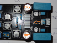
Earlier in thread I removed the little bluebox cap (gvdd) at inputsocket with no effect in any way noticable. According to some that design better layout 3116 boards this gvdd decoupling capacitor should be on ampboard, so probably just useless when 25mm to 30mm away from chippins.
This might also contribute to 4 blue bootstraps limitting what inputsignal reaches output on YJ BB. Arrow points to two pcb contacts/resistor leads where this gvdd capacitor also could be, might help getting YJ BB to perform more like other 3116 ampboards, no need to do anything if you already like YJ BB 🙂 Old (2005?) Jamicons were dry on YJ board, almost one green waterdrop of electrolyte was left in both cans, unfortunately isn't only reason board doesn't sound like any other amp.
This might also contribute to 4 blue bootstraps limitting what inputsignal reaches output on YJ BB. Arrow points to two pcb contacts/resistor leads where this gvdd capacitor also could be, might help getting YJ BB to perform more like other 3116 ampboards, no need to do anything if you already like YJ BB 🙂 Old (2005?) Jamicons were dry on YJ board, almost one green waterdrop of electrolyte was left in both cans, unfortunately isn't only reason board doesn't sound like any other amp.
Attachments
outputlevel to speakers, posters comment was 3116 could reach 17v output without trouble, but not 100watt, something like that
Data sheet Fig 26 shows 100W with 26V and 3R load for PBTL operation.
Based on that my calculation suggest that to get 100W with a 17V supply the load would have to go down to about 1.2ohms.
Based on that my calculation suggest that to get 100W with a 24V supply the load would have to go down to about 2.5ohms.
Someday when I get some test equipment built I will test the amp to see what I can get out of it.
I am using the line for 1% THD+N.
I don't use the 10% line, that is for advertising. 🙂
Colleagues, rode a DIY TPA3116D2, but I can not produce 100W when I apply 24V. The circuit works perfectly up to 17V, above this voltage the circuit does not amplify. Acretido the cause is tension in Plimit, but I can not reproduce the same characteristics of EVM in my circuit.
Has anyone had a problem like this ??
How can I fix ??
The way I read this was: 24v psu used, max output 17V into load/speaker. my reaction was this is really high for tpa3116, isn't it?
Datasheet page 16 shows TI EVM module max output with 24V PSU is 17.9V ???
Prototype: 50W @ 2 ohms = 15V (PVDD)
"Based on " my earlier calculations/assumptions 15V 2R will get you 45W.
Probably close to 50W and I would not be able to tell the difference. (0.45dB)
🙂
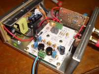
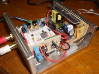
Nice compact case.
ok...Been using My YJ blue/black for a couple of months now.
Box Stock.. so far.
Did fit a Chinee Clone Alps Blu Velvet input pot,, it works well, no complaints on it.
Cut the leads on the 100k Input resistor to reduce gain
to usable levels.. some small effect 🙂.
Thanks Irrebo.
Fitted Shielded Coax input feeds to reduce RF (?) noises.. ( it worked.. Mostly)
Crappy SMPS/ laptop bricks (all genuine Brand Name ones) still input some HF noises (I've tried 12v, 19 v and 24 v bricks) 12v sounds least offensive and Power level differences are of small and in my usage, Irrelevant.
The thing remains as a bit Tinny & Harsh in the upper frequencies.
On several speakers, ALL Proven quality drivers (not a driver issue.. far from it 😉
This IS proving annoying
Anything that comes to mind to 'patch' this failing??
Last edited:
ok...Been using My YJ blue/black for a couple of months now.
...
This IS proving annoying
Anything that comes to mind to 'patch' this failing??
I tried to find pix of your setup...any posted?
ok...Been using My YJ blue/black for a couple of months now.
Crappy SMPS/ laptop bricks (all genuine Brand Name ones) still input some HF noises (I've tried 12v, 19 v and 24 v bricks) 12v sounds least offensive and Power level differences are of small and in my usage, Irrelevant.
The thing remains as a bit Tinny & Harsh in the upper frequencies.
On several speakers, ALL Proven quality drivers (not a driver issue.. far from it 😉
This IS proving annoying
Anything that comes to mind to 'patch' this failing??
Take a look at small ceramics decoupling PSU, they need to be much closer to chippins, 100nF and 10uF works for me, but 100nF-2uF might do same thing.
But there are other problems too.
Hope it isn't a driver problem in part, speakers do not happen to be 36 ohm for treble frequencies or around filterfrequency ??
I had similar experiences with this amp (YJ board mods: input transforers, bootstrap mod using ceramic smt, Coilcraft inductor etc.). It sounded certainly amazing but in the longer run something was missing - a friend calls this a certain stiffness in the presentation of music.
The other day I decided to listen to the amp again (using a Nakamichi preamp and Tannoy speakers). The impression remained the same so I decided to have a look at the caps that are part of the output LC filter - that is at their value. I don't recall the value of the Coilcraft I had fitted to the amp, but I had replaced the original 680nF caps with the value of 1uF (I admit I also don't remember which speaker I had been using at the time). Anyway, this time I decided to lower the value and - lo and behold - the occasional thiness at certain frequencies became less - so I played around with values and ended up at 100nF which - on these particular speakers and to my ears - seems to be just right. Now the amp is very transparent and neutral in the best sense of the word. If a recording is good, it sounds that way, crappy stuff - well, you can tell it ain't a masterpiece of a recording.
Obviously the correct value of the LC filter will depend (on Math which I can't get my head around enough) on one's speaker, listening preferences etc, but it's certainly worthwhile to play around with.
- Home
- Amplifiers
- Class D
- TPA3116D2 Amp