In the case of PSU caps, the KG Nichicon SuperThrough at higher voltage sound better, not because of voltage, just quality of capacitor.
I've used the Gold Tune 4700uF 35v and been very impressed, even after playing with Mundorf Mlytics in the same place (power input to board). Gold Tune is not that expensive either. Cannot say for sure that Gold Tune was better (than Mlytic) as did not do direct comparison, but that was my impression.
Last edited:
Fair enough. I would also extend the definition of "neutral" to include "unaffected by load impedance etc.". An amp with an output impedance that is so high that the frequency response gets distorted by an uneven load impedance curve is not neutral in my books.
Load impedance does influence frequency respons here, but I thought that happened always with these amps that have feedback befor outputfilter? Hypex and others have feedback after outputfilter and then have more load independent frequency respons.
Load impedance does influence frequency respons here, but I thought that happened always with these amps that have feedback befor outputfilter? Hypex and others have feedback after outputfilter and then have more load independent frequency respons.
Yes, the feedback structure does affect the output impedance and load sensitivity. Therefore the amps that don't include the output filter in the feedback loop are (in theory at least) less transparent.
I was mainly responding to Lo_Tse's statement about there not being such a thing as absolutely neutral.
So it this is exactly how TI recommends to powerup and shutdown in datasheet. SDZ is pulled low by switch, amp goes into lowcurrent state to shut down, removing power creates no pop. Giancarlo mod does have pop then and a little ''cracknoise'' on powerup. Putting the tpachip in "standby/sleep/shutdown" is only popless way IMO.
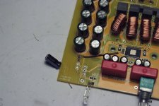
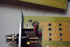
Well, with the help of a friend, I did the "anti-pop" mod, and at the same time repurposed the existing "mute" switch as a power switch , exactly as I intended.
Turn-on pop is gone (there's about 2 sec. delay on turn-on), and when turning off, there is still a slight "thump", but that one isn't that irritating or loud...
Some traces were cut, and a 10 uF cap and a 150KOhm resistor were added (see pics). Oh, and I replaced the horrendous blue LED....
So, mission accomplished. 🙂
Attachments

Well, with the help of a friend, I did the "anti-pop" mod, and at the same time repurposed the existing "mute" switch as a power switch , exactly as I intended.
Turn-on pop is gone (there's about 2 sec. delay on turn-on), and when turning off, there is still a slight "thump", but that one isn't that irritating or loud...
Some traces were cut, and a 10 uF cap and a 150KOhm resistor were added (see pics). Oh, and I replaced the horrendous blue LED....
So, mission accomplished. 🙂
So popless replaced for little pop and on/off switching DC, hardly ideal, but fun modding to personal taste.
Wow! A lot of uber nice builds lately! So lets continue on with the eyecandy😀
I received my el cheapo hifi 2.0 last week and now its almost ready! It sounds really good! I performed listenening test between each mod to get a deeper understanding of the changes. I started with the large Panasonic FK (low esr and cheap in 3300uF). They helped at lot on noise level and some on dynamics. But I guess they were too far from the chip to really make a difference. Later I added the usual oscon soldered onto the chip legs.. Huge improvement! Just as described in earlier postings!
When I added the snubber the harsness on vocals went away! The amp can't sound good with out the snubber mod.
The bootstaps were films from the factory and the amp didn't sound compressed when played loud, so I let them be.
At this point the sound didn't quite have that magic sparkle.. so I changed the input caps to my usuall trusted PPS 1uf smd caps. I am going to solder more in paralell to get atleast up to 2-3uF. That lowered the standby noise to a minimum as well giving the amp the last bit of sparkle and realism! I guess the noise has something to do with them being soldered flat on the pcb close to the ground layer.
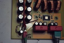
This particular board has toroids as inductors and is the only board that plays strings perfect. So I will add toroids of better and larger inductors to my other boards as well🙂
The build quality on this hifi amp is really amazing! Even better it costs only 38 usd! Machined alu front plate and knob. Mute knob and screw terminals on the back(too small). 8 screws holds it together and it's really quick to dismantle. The board has good space between the components with trough holes. Perfect for diy! As long as the RC snubber is used the extra distance doesn't matter all that much. I'll add some detailed pics for anyone one who wants to go this route🙂
Other positive things I've noticed with this board:
+wide traces on the power side and output.
+nice bootstraps
+space under the pcb to add smd components
+usable inductors
+space which allows normal size input caps
+space for psu filter caps(with large trough holes)
+large rubber feet
+really good brushed case finish
Which pins did you attach the OSCONs to, it's a little hard to see ?
I saw another user put it across where the 104 SMD caps are (0.1 uF)
Is it ok to put 330 uF caps there? Seems like a big difference 0.1 uF (noob question, I needed to ask)
And also, what caps did you replace the WIMA caps with value and type?
Help Needed, my parts arrived today - however, someone suggested this part -
TDK 220nF ±5% 50 V C0G Dielectric SMD Ceramic Multilayer Capacitor 1812
as the bootstrap capacitor.... my I have never seen anything so small, my eyesight is deteriorating and I have no idea what to do with it. I'm used to large resistors and old valve radios!!
Could someone please advise me whether it is even possible to solder this component on the Blue YJ board - I can't even see polarity! And how is the best way to do it? What also baffles me is how I'm going to implement the bootstrap snubber mod as there will be no spare wire under the board to solder onto!
cheers Stu
Help Needed, my parts arrived today - however, someone suggested this part -
TDK 220nF ±5% 50 V C0G Dielectric SMD Ceramic Multilayer Capacitor 1812
as the bootstrap capacitor.... my I have never seen anything so small, my eyesight is deteriorating and I have no idea what to do with it. I'm used to large resistors and old valve radios!!
Could someone please advise me whether it is even possible to solder this component on the Blue YJ board - I can't even see polarity! And how is the best way to do it? What also baffles me is how I'm going to implement the bootstrap snubber mod as there will be no spare wire under the board to solder onto!
cheers Stu
Actually 1812 is enormous in SMD terms! I soldered 1206 caps to te blue YJ board to replace bootstrap caps. There is no polarity.
Remove the old thru the hole blue caps. From component side put a blob of solder on one of the holes where you removed the cap. Using tweezers and very strong reading glasses (I use 3.75) place the cap one end against the solder blob, heat solder and lightly push new cap into the solder. Once done solder the other side. Repeat for other caps. Can also be done under the board if thats easier for you.
BTW, I ain't no spring chicken, just need good magnification and a steady hand.
Last edited:
Yep, magnifying glasses are mandatory for me.
Good, fine, sharp tweezers to pick up and place the part, and then to hold them down as you solder.
Soldering iron with a fine tip.
I also have a supply of copper tape, so I can make connections when I need to, a little more elegant than a solder blob, but copper tape isn't cheap.
BTW, I use something like this
Magnifier
They work very well. Only drawback is the ridicule from my teenage daughters when they see me with them on 😀
And it takes some practice, don't give up. And take a break if needed.
BTW, might be too late, but its a good idea to order extra parts. Sometimes you push down too hard when holding it in place, and next thing you know the part has flipped off your board. And if that happens, they can be hard to find.
Randy
Thanks guys, I quick visit to the poundshop for a pair 3+ glasses then!
How do I then provide contacts under the board for the bootstrap snubber mod.
The snubber mod caps 330pf have legs, would it be an idea to place these through the board from the underside so that the leg provides one side of the smd caps with somewhere to solder too?
Stu
How do I then provide contacts under the board for the bootstrap snubber mod.
The snubber mod caps 330pf have legs, would it be an idea to place these through the board from the underside so that the leg provides one side of the smd caps with somewhere to solder too?
Stu
Thanks guys, I quick visit to the poundshop for a pair 3+ glasses then!
How do I then provide contacts under the board for the bootstrap snubber mod.
The snubber mod caps 330pf have legs, would it be an idea to place these through the board from the underside so that the leg provides one side of the smd caps with somewhere to solder too?
Stu
I don't doubt you can solder the SMD caps to your board, but why risk it? Why not just get the through hole caps, and make life easier? Some have even mentioned that the bootstrap snubber mod on the existing caps offers a significant improvement without removing the existing caps. Just try the snubber mod on the existing caps and see if you like it. It's easy to remove later.
I will try the smd caps on the bootstraps (I'm too tight not to, I spent £8 on 8 caps as I have two YJ boards. I will see if I can get the snubber caps through the hole from the underside and solder the smd cap to the leg
I will take your advise Lacro if I make a mess of things first time round.
As ever this forum helps me push the boundaries of personal challenges in my hobbying, thanks for everyones input,
stu
I will take your advise Lacro if I make a mess of things first time round.
As ever this forum helps me push the boundaries of personal challenges in my hobbying, thanks for everyones input,
stu
Stu,
Look at YouTube videos of how to solder SMT parts. I found them very helpful. I use magnifying goggles with LED lights built in. Good quality Swiss made stainless steel tweezers are a must. When I made my first amp, I went with the TI recommended BOM for their EVM board. They use teeny tiny SMT parts - maybe 1/4 the size of the 1812 part you mention.
Look at YouTube videos of how to solder SMT parts. I found them very helpful. I use magnifying goggles with LED lights built in. Good quality Swiss made stainless steel tweezers are a must. When I made my first amp, I went with the TI recommended BOM for their EVM board. They use teeny tiny SMT parts - maybe 1/4 the size of the 1812 part you mention.
jk44, I bent the +pin of the Oscon cap to follow the trace that leads directly to the + chip leg. To do that I scraped of some laquer of the "+ trace" very close to the chip. I did this on both sides of the chip. The 0.1 cap is there only as a filter capacitor to remove noise, it might have lower internal resistance than the oscon, but probably not. So removing that little cap is not a problem since the new cap will do the same filtering job aswell as provide a lot of current to the chip.
If you know how to use the beep function on the multimeter the blacked out pin on the oscon cap shall beep with the earth side on psu input. The + side of the oscon shall beep with the (+) center pole on the psu input plug. After doing the mods remember to beep between the + and - to check for shorts. It should stop beeping after 1-5 seconds! The input caps I used is 1 uF film capacitors! These sound exellent! But be quick when soldering them cause the don't handle high temperatures as other caps do! (Only 340C). 5X CF057D0105KBC Film Capacitor SMD 2824 1uF 50V 10 PX 0396 | eBay
At the moment I'm waiting for new inductors to complete this amp and I will post pictures with more mods that can be done to this amp 🙂
Thanks guys, I quick visit to the poundshop for a pair 3+ glasses then!
How do I then provide contacts under the board for the bootstrap snubber mod.
The snubber mod caps 330pf have legs, would it be an idea to place these through the board from the underside so that the leg provides one side of the smd caps with somewhere to solder too?
Stu
Leadspacing original through-hole bootstraps is 5 mm, size of this ceramic is ~4.5 mm, so fits nicely on existing solderpads topside. If you could solder without special glasses the 5 mm, you can solder these🙂
I don't doubt you can solder the SMD caps to your board, but why risk it? Why not just get the through hole caps, and make life easier? Some have even mentioned that the bootstrap snubber mod on the existing caps offers a significant improvement without removing the existing caps. Just try the snubber mod on the existing caps and see if you like it. It's easy to remove later.
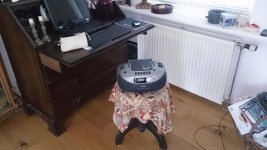
This little gem🙂 really has more detailed playback than YJblue with original bootstraps. It started out as a joke when 3 of us were listening to 3 different 3116's and host said he could not imagine a portable would have less detail and after he searched a little he came back with this dusty Casio.
Anything you replace on YJblue might give an significant improvement, but just replacing bootstraps will let the Casio eat dust, listening to same cd and to same detail.
Attachments
At least the YJ blue/black board uses film capacitors as input capacitors and on the wiki there are a couple of recommendations as well. TPA3116 datasheet doesn't say anything about the capacitor type, but the TPA3110 datasheet says as follows: " ...a low-leakage tantalum or ceramic capacitor is the best choice."
Both my Sure 3110 (2x15W) and 3116 seem to have some surface mount capacitors (but possibly nothing on negative/ground side?)... So, is there some specific sound quality reason for using film capacitors? Ethical reasons against tantalum? Film capacitors having a higher voltage rating?
Shipping costs for Mouser or Digikey are kind of expensivish for me so I'm sort of limited to what RS and my local shops have available. The selection of suitable 10uF capacitors is kind of limited so I would like to know what I would be missing by using another type of capacitor...
This little gem🙂 really has more detailed playback than YJblue with original bootstraps. It started out as a joke when 3 of us were listening to 3 different 3116's and host said he could not imagine a portable would have less detail and after he searched a little he came back with this dusty Casio.
Anything you replace on YJblue might give an significant improvement, but just replacing bootstraps will let the Casio eat dust, listening to same cd and to same detail.
How can you possibly compare a YJ blue modded or unmodded running good speakers with a $30 boom box?
I still have yet to try a bootstrap cap upgrade - my Ybdz uses small SMT ceramics currently and they are not the easiest things to replace. Perhaps they already are C0G ceramics so is there a point? Has anyone changed bootstrap caps on Ybdz?
- Home
- Amplifiers
- Class D
- TPA3116D2 Amp