Whatever sounds best, is best.
Yes, you can always go up on voltage of a capacitor. It's down when they pop.
Yes, you can always go up on voltage of a capacitor. It's down when they pop.
Yes, you can always go up on voltage of a capacitor. It's down when they pop.
I've always assumed capacitor voltage rating should be higher than actual working voltages, for some safety margin.
Is there any rule of thumb for how much higher the cap voltage should be?
I've always assumed capacitor voltage rating should be higher than actual working voltages, for some safety margin.
Is there any rule of thumb for how much higher the cap voltage should be?
I'm not a professional, but I've read somewhere that double is a safe bet.
According to TI in a more specific datasheet for newer chip:
For all powersupply caps, decoupling, bootstrap, GVDD >1.45 times DC voltage PSU.
For filter capacitor in output >1.8 times DC voltage PSU.
For all powersupply caps, decoupling, bootstrap, GVDD >1.45 times DC voltage PSU.
For filter capacitor in output >1.8 times DC voltage PSU.
Only the amount of DC a CD player or such would put out, not any home brew stuff.
I contacted Cinemag, their transformers will work like an input capacitor, unless it's significant DC, like if your DCB1 had a failure perhaps. But even then, you turn it off and repair.
Interesting. Wonder if they have a small gap to handle small DC currents.
Irribeo,
Nope, I don't have any edcor signal trannys. I do have one of their power trannys for a future project whenever I get to it.
Randy
Thanks for the LED help Skylab! So I've ordered another blue board as I'm hearing its potential now, it seems to have got better since first powering it up. I've taken the plunge and ordered the mod parts recommended here (and another board in case of mistakes!)
I used RS Online in the UK as they are cheap on delivery so I messed with a few recommendations but am posting bill of parts in case it helps someone:
DC Power caps - Panasonic Oscons 25SEPF330M
Bootstrap Snubber mod - WIMA 0.00033 μF ±5 % 100 V dc Polypropylene Film Capacitor
.................................and ...Vishay MRS16 Axial Thin Film Resistor 10Ω ±1% 0.4W
Bootstrap capacitors - TDK 220nF ±5% 50 V C0G Dielectric SMD Ceramic Multilayer Capacitor 1812
Input Signal DC De-coupling Caps - WIMA 4.7 μF ±10 % 100 V dc, 63 V ac Through Hole Polyester Film Capacitor - hoping these won't increase any popping that is not really audible at the moment
and finally I'm putting a low pass shelve filter in the signal as one of the amps is driving some ceiling speakers that need a tweak to the EQ:
Parts for filter:
WIMA 0.047 μH ±10 % 160 V ac, 250 V dc Through Hole Polyester Film Capacitors
4k7 metal film resistors
Voila, will report back with progress, I know I'm just repeating what's been mentioned ALOT in this thread but it will be a minor achievement for me and as I always say " thanks to all the contributions from everyone"
stu
Anti-pop on HIFI board?
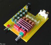
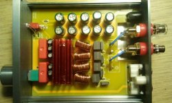
Has anyone done anything regarding the turn-on pop supression on the HIFI board (boxed "HIFI" amp) - like the one in the attached photos?
It's a nice amp in a nice enclosure, but I don't like two things about it: instead of power switch, it has a "Mute" switch, and it has a turn-on pop (and a turn-off pop, but that one is not so irritating)... 🙁
Power switch would be better and would avoid arcing when connecting the power cord at the connector on the back... and the mute could be implemented similar to "Giancarlo mod" - by adding 4,7 - 10 uF cap plus a resistor (not sure if a diode is necessary).
And mine has an irritating blue LED - that, at least, is easily replaced 🙂
So, has anyone done an anti-pop solution for this board?
As a sidenote, this one doesn't have "TRIBLE" and "VOLVME" issues, but has "SPERKERS" instead
Attachments
Has anyone done anything regarding the turn-on pop supression on the HIFI board (boxed "HIFI" amp) - like the one in the attached photos?
It's a nice amp in a nice enclosure, but I don't like two things about it: instead of power switch, it has a "Mute" switch, and it has a turn-on pop (and a turn-off pop, but that one is not so irritating)... 🙁
Power switch would be better and would avoid arcing when connecting the power cord at the connector on the back... and the mute could be implemented similar to "Giancarlo mod" - by adding 4,7 - 10 uF cap plus a resistor (not sure if a diode is necessary).
And mine has an irritating blue LED - that, at least, is easily replaced 🙂
So, has anyone done an anti-pop solution for this board?
As a sidenote, this one doesn't have "TRIBLE" and "VOLVME" issues, but has "SPERKERS" instead
Is it a mute switch? If you use switch and then remove power is there pop? If you put power on amp with switch in off position, is there pop then?
Is it a mute switch? If you use switch and then remove power is there pop? If you put power on amp with switch in off position, is there pop then?
The existing switch is a "MUTE" switch (although it says "power" on the faceplate). When the swich is activated, there is no sound. So, if you turn on the amp (i.e. plug in the power cord), there is no sound at all - including no pop.
However, then you have arcing on the back, when plugging in the power cord 🙁
Besides, it would be much more practical to have this switch act as power switch, and the turn-on pop muting implemented using a small cap and a resistor ("Giancarlo mod").
Also, the small LED is always on, as long as the power cord is plugged in - meaning that the amp is powered. All points to the fact that this was indeed supposed to be a power switch, but someone decided to do it this way.
This would be the first (and most likely the only) mod I'll do on this board: I was thinking of adding another physical switch as a power switch, but that's an overkill (TWO switches tend to be confusing). Repurposing the mute switch to act as power switch would be much better - and the "turn-on pop" muting would be implemented the usual way ("retarding" cap)...
Thanks guys for the inputs 🙂
Hi jk44, I have 470uF 35v Silmic II Black 25mm x 35mm. It's big, but I am building a new case for this project so it can be put together with Sigma 11 Regulated PSU.
I am thinking of Silmic II because base on my experience in my audio setup, it will reduce the high range peak and midrange roughness, also increase lower range richness which may solve the problem I am having.
For input caps, I am thinking of Wima MKP10, but hard to source it bigger than 1uF. Anyway, I do have 3.3uF Rike Audio S caps on hand. I may try those 😀
From what I understand, the Power supply filter caps should be high quality low-ESR, power-filtering intended caps as opposed to Audio grade caps. However Silmic do rate pretty well and may work, what size are you trying to fit in? I only have 50V caps that are 16mm, a little too wide for those spots on the PCB.
I also found getting rid of those Green "Vishay" input caps and using a genuine set of caps there. I got the Panasonic Metalized Polyester 10 uF/100V recommended on the TPA3116D2 wiki (TPA3116D2 Boards - diyAudio), it definitely added some sparkle and clarity to the sound. Haven't had a chance to listen critically, as I'm jumping between two TPA3116 amp projects at the moment
Hi jk44, I have 470uF 35v Silmic II Black 25mm x 35mm. It's big, but I am building a new case for this project so it can be put together with Sigma 11 Regulated PSU.
I am thinking of Silmic II because base on my experience in my audio setup, it will reduce the high range peak and midrange roughness, also increase lower range richness which may solve the problem I am having.
For input caps, I am thinking of Wima MKP10, but hard to source it bigger than 1uF. Anyway, I do have 3.3uF Rike Audio S caps on hand. I may try those 😀
For input caps, I am thinking of Wima MKP10, but hard to source it bigger than 1uF. Anyway, I do have 3.3uF Rike Audio S caps on hand. I may try those 😀
I used 2.2uf MK10, got 'em off Ebay, last I looked there were still some available.
I used 2.2uf MK10, got 'em off Ebay, last I looked there were still some available.
Thanks for the info mate. I need to do some more shopping again. Since I have had this hobby, my salary turns into some components 😀
re: transformer or no transformer
has anyone used a Balanced minidsp as input, and bypassed the input caps?
has anyone used a Balanced minidsp as input, and bypassed the input caps?
For a transducer (such as a speaker) I would agree, but for a transformer there is an easy standard for "neutral" - a transformer is neutral when the output signal is the same as the input signal.
Well, I agree with you in theory. Unfortunately, when the component or equipment is within a chain, it is very difficult to determine how it is interacting with other parts. An amplifier can be "very neutral by itself" based on measurement However, when you pair it with certain speakers, it may not give you the sound that you expected.
Regards,
re: transformer or no transformer
has anyone used a Balanced minidsp as input, and bypassed the input caps?
That is a great question. I just ordered another unbalanced miniDSP and wonder if I should have done it the other way.
Has anyone done anything regarding the turn-on pop supression on the HIFI board (boxed "HIFI" amp) - like the one in the attached photos?
It's a nice amp in a nice enclosure, but I don't like two things about it: instead of power switch, it has a "Mute" switch, and it has a turn-on pop (and a turn-off pop, but that one is not so irritating)... 🙁
Power switch would be better and would avoid arcing when connecting the power cord at the connector on the back... and the mute could be implemented similar to "Giancarlo mod" - by adding 4,7 - 10 uF cap plus a resistor (not sure if a diode is necessary).
And mine has an irritating blue LED - that, at least, is easily replaced 🙂
So, has anyone done an anti-pop solution for this board?
As a sidenote, this one doesn't have "TRIBLE" and "VOLVME" issues, but has "SPERKERS" instead
I have the same board, it is a very good sounding board just remember to mute it before turning on/off then no pop.
I've always assumed capacitor voltage rating should be higher than actual working voltages, for some safety margin.
Is there any rule of thumb for how much higher the cap voltage should be?
I've seen some discussion on it. I wouldn't get concerned. There's basically not going to be a situation where it matters. Usually it costs more $, so no one's doing much except trying to not exceed the capacitor limits because it's cheaper.
In the case of PSU caps, the KG Nichicon SuperThrough at higher voltage sound better, not because of voltage, just quality of capacitor.
The existing switch is a "MUTE" switch (although it says "power" on the faceplate). When the swich is activated, there is no sound. So, if you turn on the amp (i.e. plug in the power cord), there is no sound at all - including no pop.
However, then you have arcing on the back, when plugging in the power cord 🙁
Besides, it would be much more practical to have this switch act as power switch, and the turn-on pop muting implemented using a small cap and a resistor ("Giancarlo mod").
Also, the small LED is always on, as long as the power cord is plugged in - meaning that the amp is powered. All points to the fact that this was indeed supposed to be a power switch, but someone decided to do it this way.
This would be the first (and most likely the only) mod I'll do on this board: I was thinking of adding another physical switch as a power switch, but that's an overkill (TWO switches tend to be confusing). Repurposing the mute switch to act as power switch would be much better - and the "turn-on pop" muting would be implemented the usual way ("retarding" cap)...
So it this is exactly how TI recommends to powerup and shutdown in datasheet. SDZ is pulled low by switch, amp goes into lowcurrent state to shut down, removing power creates no pop. Giancarlo mod does have pop then and a little ''cracknoise'' on powerup. Putting the tpachip in "standby/sleep/shutdown" is only popless way IMO.
To bypass 1 set of dcblocking capacitors you might not need balanced board. Last time I looked at minidsp it had large electrolytic's in output to block dc. You connect those with 20cm?? interconnect to the dc blocking inputcapacitors on tpa3116. I don't know if that is changed on minidsp and if those dcblocking electrolytics were bipolar but probably a lot of information in other threads I do not know 🙂That is a great question. I just ordered another unbalanced miniDSP and wonder if I should have done it the other way.
Well, I agree with you in theory. Unfortunately, when the component or equipment is within a chain, it is very difficult to determine how it is interacting with other parts. An amplifier can be "very neutral by itself" based on measurement However, when you pair it with certain speakers, it may not give you the sound that you expected.
Fair enough. I would also extend the definition of "neutral" to include "unaffected by load impedance etc.". An amp with an output impedance that is so high that the frequency response gets distorted by an uneven load impedance curve is not neutral in my books.
- Home
- Amplifiers
- Class D
- TPA3116D2 Amp