The oscillator frequencies should be the same or you will get hetrodyning of the two frequencies...a difference in the two will be heard.
Somewhere in this thread there are the correct values for the R and the C...not the ones in the data sheet.
Happy hunting.
Somewhere in this thread there are the correct values for the R and the C...not the ones in the data sheet.
Happy hunting.
Why does the clock need to be sync'd to share a power supply? I know TI shows in their datasheet a master/slave for a 2.1 config.
Exactly.
Pardon my ignorance but I really do not see why something has to be done when two "identical amps" are connecting to one power supply. How does it different as compare to connecting the left and right channels of an amp to the PS?
Regards,
Doug, This is very valuable information that I had not heard before. I guess it's true for all class D amps connected to 1 PSU? How exact do the frequencies need to be (or shall I say, how far apart) before this hetrodyning can be heard? Is all that's required are the same values for R and C?The oscillator frequencies should be the same or you will get hetrodyning of the two frequencies...a difference in the two will be heard.
Somewhere in this thread there are the correct values for the R and the C...not the ones in the data sheet.
Happy hunting.
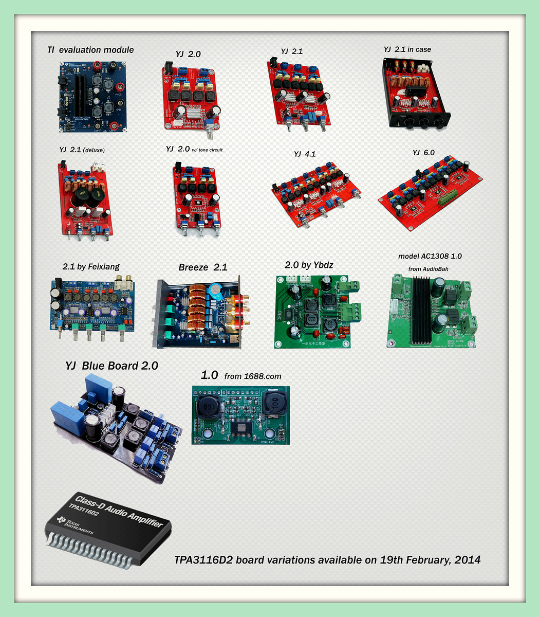
I refer to the board from 2.0 chengzhi, that the one I say that uses the same components as the feixang 2.1, thats Why I believe its not from Chengzhi and its from feixang.Which board are you referring to when you say "Little Blue One"? The "Danzz" YJ 2.0 Blue Board? Or the Feixiang 2.1?
The oscillator frequencies should be the same or you will get hetrodyning of the two frequencies...a difference in the two will be heard.
Somewhere in this thread there are the correct values for the R and the C...not the ones in the data sheet.
Happy hunting.
Dug,
Great info here - never thought of that. Even though the oscillator freq is 400kHz, if they are off by 30Hz you will hear a 30Hz beat note!
What if I am bi-amping with two class D amps and they have separate power supplies but driven by same source? Is the heterodyning (or beat freq) an issue if the PS is the same or the SOURCE is the same? Or both?
Thanks,
X
I have some of the ChengZhi boards on the way. I hope it's not as bad as they say.
I've added the ChengZhi board back into the mix until the information is clarified concerning this board.
Attachments
Dug,
Great info here - never thought of that. Even though the oscillator freq is 400kHz, if they are off by 30Hz you will hear a 30Hz beat note!
What if I am bi-amping with two class D amps and they have separate power supplies but driven by same source? Is the heterodyning (or beat freq) an issue if the PS is the same or the SOURCE is the same? Or both?
Thanks,
X
I don't know...please try it and let us know.
I would guess that with separate supplies there would not be an issue.
Did anyone find the post with the correct values?
I will have 4 of the blue boards on one supply. This sync issue may get interesting.
Cheers,
Rod
Cheers,
Rod
I will have 4 of the blue boards on one supply. This sync issue may get interesting.
Cheers,
Rod
Slave 3 to one.
Slave 3 to one.
Hey, DUG
Can you elaborate why connecting 2 amps to one PS would cause issues? I can see that in this scenario, the two amp are "linked" at the PSU connection. Through what mechanism does the 2 amps start "talking" to each other?
Thanks!
Regards,
Hey, DUG
Can you elaborate why connecting 2 amps to one PS would cause issues? I can see that in this scenario, the two amp are "linked" at the PSU connection. Through what mechanism does the 2 amps start "talking" to each other?
Thanks!
Regards,
Power supply modulation.
May be minor but you want to avoid the hetrodyning.
Sync makes it possible.
Power supply modulation.
May be minor but you want to avoid the hetrodyning.
Sync makes it possible.
Makes perfect sense. We're dealing with switching amplifiers at drawing power from the same supply. I just wonder who will be willing to sacrifice two or more TAP3116 amp modules to test this out. 😕
Makes perfect sense. We're dealing with switching amplifiers at drawing power from the same supply. I just wonder who will be willing to sacrifice two or more TAP3116 amp modules to test this out. 😕
LOL
Does not need to be a sacrifice...just disconnect (or don't connect) the sync section.
And listen.
There is another way:
Use the oscillator frequency selection to select a different frequency on the 2nd, 3rd modules, etc..
Just make sure the filter inductors have a higher self resonance frequency than your oscillator.
(and the filter caps as well.)
Last edited:
Slave 3 to one.
That's what I will do when they arrive. Thanks Dug.
Does anyone have the Blue boards yet? If so would be interesting to know if they brought the syncing connections to pads for wiring between amps?
Cheers,
Rod
Last edited:
That's what I will do when they arrive. Thanks Dug.
Does anyone have the Blue boards yet? If so would be interesting to know if they brought the syncing connections to pads for wiring between amps?
Cheers,
Rod
You also have to change the resistor at the gain/slave pin, to the slaves IC, as depending of the resistors the IC determines that its slave and then the sync pin its an input, otherwise wont work.
Check the datasheet
You also have to change the resistor at the gain/slave pin, to the slaves IC, as depending of the resistors the IC determines that its slave and then the sync pin its an input, otherwise wont work.
Check the datasheet
Very good point.
I knew there was some "minor" detail that was important.(that I forgot)
🙂
You also have to change the resistor at the gain/slave pin, to the slaves IC, as depending of the resistors the IC determines that its slave and then the sync pin its an input, otherwise wont work.
Check the datasheet
Thanks very much danzz. I had seen that in the datasheet. Will make up a little schematic and post it here before I wire it. But first will just breadboard one of the amps to get a good feel for it. I'm getting excited now - really looking forward to hearing these little guys!
Cheers,
Rod
Power supply modulation.
May be minor but you want to avoid the hetrodyning.
Sync makes it possible.
DUG,
Thanks!
So a quick solution will be use two PSU's? One for each amp in PBTL mode?
Regards,
To enable or disable the SYNC option you need to change the 2 gain voltage divider resistors. This can be done easily if the desired gain setting is either 26dB (normal gain for home stereo equipment), 32dB (gain for portable music players), or 36dB (gain for very low output portable devices) by having 3 resistors instead of 2 and changing the connection point for the GAIN/SLV input to either side of the middle resistor.
26dB gain: R1=20K, Rm=56K, and R2=47K. Resistor value is then either 20K/103K or 76K/47K
32dB gain: R1=39K, Rm=62K, and R2=39K. Resistor value is then either 39K/101K or 101K/39K
36dB gain: R1=47K, Rm=56K, and R2=18K. Resistor value is then either 47K/74K or 103K/18K
All these values should be close enough that you can still use 5% parts but for added safety you can choose resistors with more narrow tolerances.
You can also use a string of 5 or more resistors if you want to be able to both change gain setting and slave/master setting.
For example, you could want the choice between 26dB and 36dB gain options as that would be the typical settings for either home use or portable system use. The middle of the road 32dB setting is generally a little high for home use and a little low for portable use, although a good compromise for an all-round system.
In that case you'll need 5 resistors. R1a=20K, R1b=27K, Rm=27K, R2a=30K R2b=18K to get 20K/102K, 47K/75K, 74K/48K, and 104K/18K.
Last edited:
To enable or disable the SYNC option you need to change the 2 gain voltage divider resistors. This can be done easily if the desired gain setting is either 26dB (normal gain for home stereo equipment), 32dB (gain for portable music players), or 36dB (gain for very low output portable devices) by having 3 resistors instead of 2 and changing the connection point for the GAIN/SLV input to either side of the middle resistor.
26dB gain: R1=20K, Rm=56K, and R2=47K. Resistor value is then either 20K/103K or 76K/47K
32dB gain: R1=39K, Rm=62K, and R2=39K. Resistor value is then either 39K/101K or 101K/39K
36dB gain: R1=47K, Rm=56K, and R2=18K. Resistor value is then either 47K/74K or 103K/18K
All these values should be close enough that you can still use 5% parts but for added safety you can choose resistors with more narrow tolerances.
You can also use a string of 5 or more resistors if you want to be able to both change gain setting and slave/master setting.
For example, you could want the choice between 26dB and 36dB gain options as that would be the typical settings for either home use or portable system use. The middle of the road 32dB setting is generally a little high for home use and a little low for portable use, although a good compromise for an all-round system.
In that case you'll need 5 resistors. R1a=20K, R1b=27K, Rm=27K, R2a=30K R2b=18K to get 20K/102K, 47K/75K, 74K/48K, and 104K/18K.
If flexibility is the goal, may be one could use a 100K potentiometer and calibrate the turn.
Regards,
- Home
- Amplifiers
- Class D
- TPA3116D2 Amp