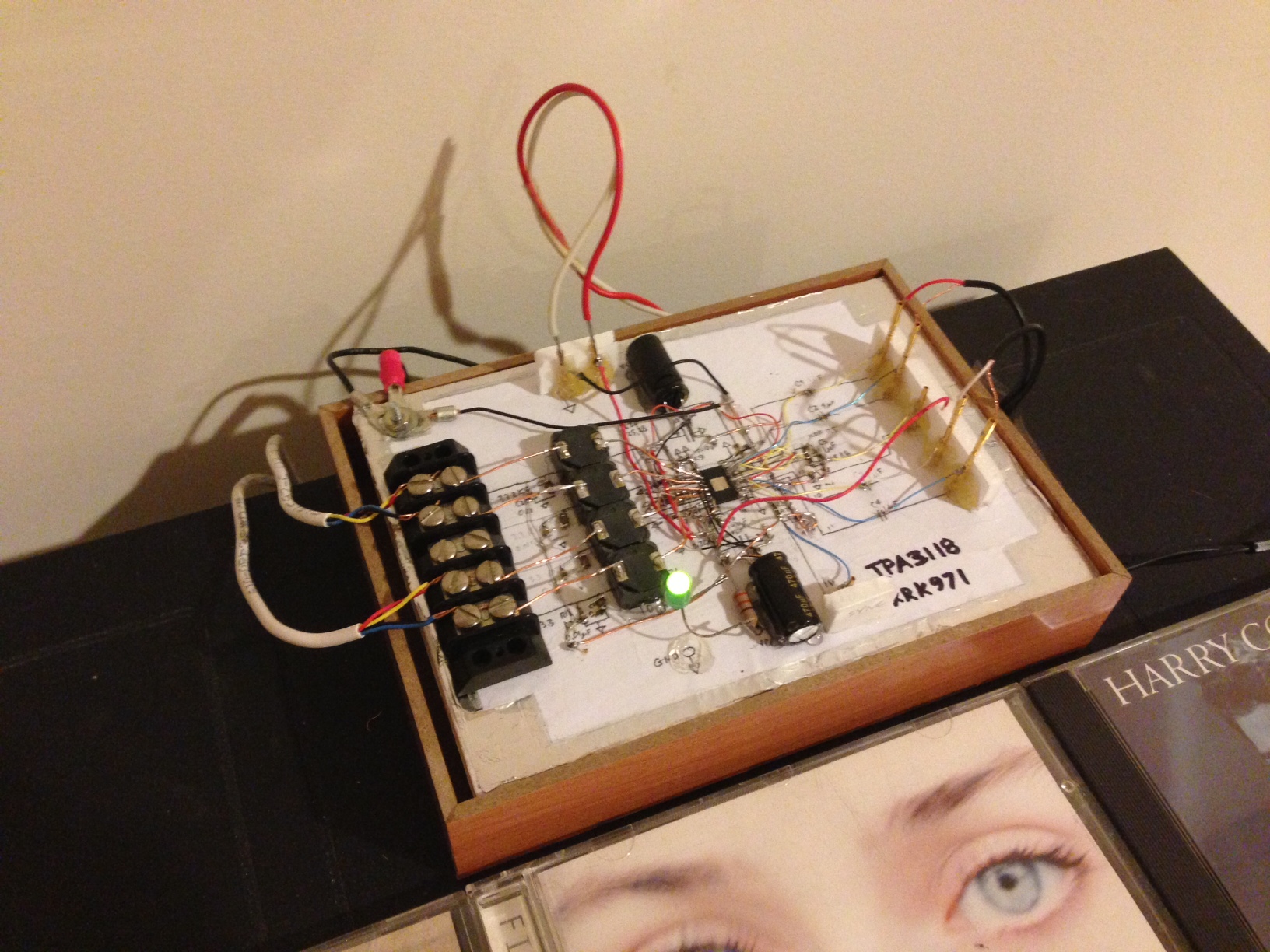
Yes, but is this your amp of choice, or just proof of concept? 🙂You guys are poo poo'ing this big thru hole board based on the fact that the traces are long and components are big. I am not so sure it makes a big difference. Have you actually heard what this board sounds like before relegating it to the dustheaps of poor sounding designs? I only say this because if you recall I was one of the first to build a tpa3118d2 dead bug style with point to point wiring. I used small SMT components but it was far from an ideal layout and it sounded great. I think it is important to keep the leads between the chip and the inductor as short as possible and keep the power supply bypass caps as close to the chip as possible. But I am not sure if there is detectable effect on SQ if they are a little longer. I would reserve judgement until someone buys one and tests it and listens to it.
Here is the dead bug amp
Sure it is, great job !
Let me know when you will have these availabl... Even better if the IC comes already soldered. 🙂 Seriously, I am interested.
[]'s
I will have to find a cheaper source...my cost is more than $5.50 ea in qty of 50.
I'll second an order for your board dug. I'd love to try my hand at building one with TI spec high quality components.
I expect to have the best value for the money.
Obviously it is a good playground for those who have no smt soldering experience but want to experiment on changing components and modding the board to the ultimate, ending with crap sound. In the end it will sound worse, no matter how much you mod it, this board is made for a slow circuit that will work like an antenna grabbing junk and for $8.00 $ 14.00 I would sure take the YuanJing.
You are free to take your chances but people should be aware that this board is a bad design and one of the worse competitors if not the worse, sound quality wise.
well now i definitely have to get one.
Last edited:
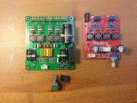
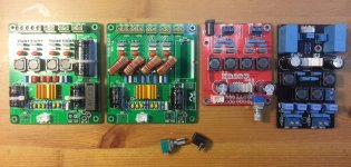
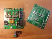
Real Size Comparison
Real Size Comparison more details
Something close to what you can see by the picture.
With the yj boards I still have hiss even with 87dB speakers.
[]'s
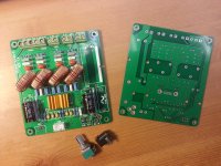
Real Size Comparison more details
Attachments
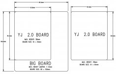
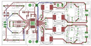
Top and Bottom PCB Layout Design
This board is special design for my friend only, as he need it over 100pcs for field application. The height is limited by <21mm, therefore, No better solution for the PSU cap placement. We are tested a lot of digital amps solutions from 50W ~150W power range. Finally, The TPA3116 solution is best. As simple, lower power requirements and High Efficiency, Totally out of our imagine and within the budget. We are also compared all the existing TPA3116 boards in market (Boards all from China). Therefore, Do as our flavor .
Sharing the layout design as this is first sample.
No, thank you. Sometimes I feel the same.
100% agreed, it seems he has succeed.
I like through hole for the output filters if you can keep legs short on a good designed pcb, then it may be a good compromise.
With this board there are way too many problems summing up
+ Freaking long tracks
+ Electrolytic caps put on vertical with ridiculous long legs
+ Filling empty space with copper is not always a good idea.
+ Distance between critical components is much bigger than the recommended by TI.
+ Through hole components on a poor designed PCB.
Some one with the right skills can design a TPA3116 based amp with through hole components while avoiding most of the problems. This is definitely not the case with this board.
This board is the best bag for the buck IF you are starting on the diy world and/or would like to try, experiment and make changes at will with through hole components.
Good cheap "eval board" with long tracks, plenty of space.
Sure, the more experienced guys will have something to add about this board and I am curious to hear from em.
This board is special design for my friend only, as he need it over 100pcs for field application. The height is limited by <21mm, therefore, No better solution for the PSU cap placement. We are tested a lot of digital amps solutions from 50W ~150W power range. Finally, The TPA3116 solution is best. As simple, lower power requirements and High Efficiency, Totally out of our imagine and within the budget. We are also compared all the existing TPA3116 boards in market (Boards all from China). Therefore, Do as our flavor .
Sharing the layout design as this is first sample.
Attachments
Ha ha, you designed all three didn't you ? 😀
No, Just the Big Board is my designed.
Now doing the new layout and take out the PSU Cap and reduce the board size. This new board for my new system.
Yes, but is this your amp of choice, or just proof of concept? 🙂
Hi,
No Heatsink and TPA3116 Thermal PADS (TOP and Bottom) Connect to GND for best system performance
Real Size Comparison more details
So how do I order one of your boards?
Real Size Comparison more details
Well, in my photoshop "simulation "I missed by half a centimeter or something close to that 🙂
Alright, so the green board that I am trying to sank into oblivion is 10x9cm versus 61x81cm of the yuan jing board vs 6.5x5.6cm of the DUG board. All being 2.0 channels 2x50W 😀
________________
Man, make a board with dimensions bellow 6.5x6.5cm, smt components but X7R 250V caps for the bootstrap and a nice mute terminal . No need for volume pot or tank caps... just like the DUG design...
Well, you have a PM.
No, Just the Big Board is my designed.
Now doing the new layout and take out the PSU Cap and reduce the board size. This new board for my new system.
😀 ouch
Well, in my photoshop "simulation "I missed by half a centimeter or something close to that 🙂
Alright, so the green board that I am trying to sank into oblivion is 10x9cm versus 61x81cm of the yuan jing board vs 6.5x5.6cm of the DUG board. All being 2.0 channels 2x50W 😀
________________
Man, make a board with dimensions bellow 6.5x6.5cm, smt components but X7R 250V caps for the bootstrap and a nice mute terminal . No need for volume pot or tank caps... just like the DUG design...
Well, you have a PM.
Yes, target is 6.5x6.5 to minimize the size fit into chassis.

Yes, target is 6.5x6.5 to minimize the size fit into chassis.
Alright, you are a nice guy.
Please, check your private messages by clicking here
Yes, but is this your amp of choice, or just proof of concept? 🙂
Proof of concept as I had to flip chip upside down with legs up on dead bug and needed thermal pad on bottom which was now, up facing.
This one small and tight enough?
2.53" x 2.20"
Very nice Dug! I am still waiting for my Chinese board to arrive but I believe your design is the ideal layout and with ideal components. It will be interesting to compare.
This one small and tight enough?
2.53" x 2.20"
I'd buy several boards (3-4) should this one go into production 🙂
The more I look to the New YJ board, the more its looks to the design I posted in post #941...
If they have copy my design, they should had read Saturnus what suggested...😀...
Well, I suspected when the different boards are optimized, they will look quite similar. The circuit for this amp is not that complicated (as compare to some other amps) and when squeeze down onto a small PCB, there are only that many ways to package all the component.
I guess one can safely assume that all the boards are designed based on the one that TI originally published.
Regards,
- Home
- Amplifiers
- Class D
- TPA3116D2 Amp