I thin the confusion on the YJ board is that they are logically changed. The side that has the right input has the left output and the side that has the left input has the right output. Doesn't necessarily mean they are changed around though.
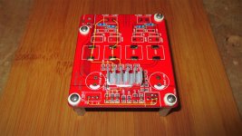
If you put the card with inputs on top it reads:
L - 0 - R, for the inputs and
R- - R+ - L- - L+, for the outputs.
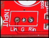
Well the bottom line is that the audio signal fed into the "Right" Channel input pin on the little white input header is output from the Left Channel output terminals and the audio signal fed into the "Left" Channel input pin on the little white input header is output from the "Right" Channel output terminals.
.....so if you follow the input and output markings that are on the board... The left and right channels are swapped. You can use a test disc with a channel assignment track to confirm.
I've done some extra tests and you are right, I was wrong.
Right input goes to left output. Left input goes to right output.
I didn't have any problems because my soundcard is inverting the balance :s. So it got inverted twice, that means it went back to normal 😉
Serious ?
I mean, look at the size of this board

This amplifier has enough of hiss with smt components on a tiny PCB.
This big board with lots of trough hole components and the extra, unused pcb space is only going to provide you with much more parasitic inductance, hiss and crap...
This board is exactly what we should avoid .
Thank you, I thought I was talking into a vacuum!

High frequency, power-supply bypass capacitors should be small size, SMD and as close to the chip as possible.
Long trace, long lead and self-inductance of the cap will create too much inductance and swamp any very-high frequency bypassing of the cap.
Remember, this is a digital chip working at very high frequencies, it needs digital power-supply bypassing.
Through hole for gain and other user selectable parameters is fine, nay great for DIY but NOT power-supply!
Those OrangeDrop looking caps are pretty but they physically and electrically CANNOT address digital high frequencies.
And see how the main PS caps are sideways! The long leads to the ground plane would swamp any low-ESR caps you're using?!?! This designer is trying to seduce the DIYer with audiophoolery, NOT follow proper digital design procedures.
Hey Virpz, what other components are high-freq critical? Output filter?
Cheers,
Jeff
Last edited:
Something close to what you can see by the picture.
With the yj boards I still have hiss even with 87dB speakers.
[]'s
Hmm. It is quite a bit larger.
Regards,
I'll take my chances.
wushuliu,
Please let's us know your feedback on these "big boards" if you decided to try it.
Regards,
How much worse could they really be for $8.00-$14.00! 🙂 I mean, really. What do we expect the performance of these little boards to be!? Most of us probably add more noise just by the way we hook it up and the routing of cables. 😉Serious ?
I mean, look at the size of this board
This amplifier has enough of hiss with smt components on a tiny PCB.
This big board with lots of trough hole components and the extra, unused pcb space is only going to provide you with much more parasitic inductance, hiss and crap...
This board is exactly what we should avoid .
How much worse could they really be for $8.00-$14.00! 🙂 I mean, really. What do we expect the performance of these little boards to be!? Most of us probably add more noise just by the way we hook it up and the routing of cables. 😉
I expect to have the best value for the money.
Obviously it is a good playground for those who have no smt soldering experience but want to experiment on changing components and modding the board to the ultimate, ending with crap sound. In the end it will sound worse, no matter how much you mod it, this board is made for a slow circuit that will work like an antenna grabbing junk and for $8.00 $ 14.00 I would sure take the YuanJing.
You are free to take your chances but people should be aware that this board is a bad design and one of the worse competitors if not the worse, sound quality wise.
Last edited:
I've done some extra tests and you are right, I was wrong.
Right input goes to left output. Left input goes to right output.
I didn't have any problems because my soundcard is inverting the balance :s. So it got inverted twice, that means it went back to normal 😉
Cool, mystery solved! 🙂
This image shows the signal path clearly. If the screenprinting at the input were changed to this second photo, all would be correct since the Left and Right designations within the chip are arbitrary.
Attachments

I'm running some Radio Shack 40-1354 full range drivers. I hooked it up last night with some tweaking of the input caps, just some 25v 1000uh nichicon I found on a junked board at the goodwill. Not audio quality or muse or anything though so that's probably definitely not the right mod but hey thought I'd try something different. I also replaced the output inductors with these I had laying around from an almost successful lepai 2020a+ mod....
744732100 Wurth Electronics | Mouser
I have some of these... ECW-FD2W225J4 Panasonic | Mouser
should I try bringing the signal in at the #4 and #10 pins as recommended on page 11 or so by KJA or are these all wrong?
I tried running some rock songs where a nice bass line will come in while other instruments stop playing and it almost sounds like the amp is preventing the lower frequencies from coming thru. I have a second red yj board I should hook up to see if maybe I got a lemon but haven't had time yet.
It also sounds like quite a few of you are either electronic engineers or have extensive experience so I'm having a hard time following/sourcing all the proper mod parts although I'm learning. Regardless it's fun so I'll keep screwing around till I figure something out or ruin the board which it more likely. 😀
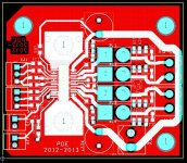
View attachment 396631 What do you think of the layout of this board?
Find a bigger pic or a link to a bigger pic!

I expect to have the best value for the money.
Obviously it is a good playground for those who have no smt soldering experience but want to experiment on changing components and modding the board to the ultimate, ending with crap sound. In the end it will sound worse, no matter how much you mod it, this board is made for a slow circuit that will work like an antenna grabbing junk and for $8.00 $ 14.00 I would sure take the YuanJing.
You are free to take your chances but people should be aware that this board is a bad design and one of the worse competitors if not the worse, sound quality wise.
Based on your predicted crappy performance of this board, I am quite tempted to buy one, just to see how bad it could be. Kind of use it as a"negative reference standard".
Regards,
No, thank you. Sometimes I feel the same.Thank you, I thought I was talking into a vacuum!
This designer is trying to seduce the DIYer with audiophoolery.
100% agreed, it seems he has succeed.
Hey Virpz, what other components are high-freq critical? Output filter?
I like through hole for the output filters if you can keep legs short on a good designed pcb, then it may be a good compromise.
With this board there are way too many problems summing up
+ Freaking long tracks
+ Electrolytic caps put on vertical with ridiculous long legs
+ Filling empty space with copper is not always a good idea.
+ Distance between critical components is much bigger than the recommended by TI.
+ Through hole components on a poor designed PCB.
Some one with the right skills can design a TPA3116 based amp with through hole components while avoiding most of the problems. This is definitely not the case with this board.
This board is the best bag for the buck IF you are starting on the diy world and/or would like to try, experiment and make changes at will with through hole components.
Good cheap "eval board" with long tracks, plenty of space.
Sure, the more experienced guys will have something to add about this board and I am curious to hear from em.
Based on your predicted crappy performance of this board, I am quite tempted to buy one, just to see how bad it could be. Kind of use it as a"negative reference standard".
Regards,
I will quote myself 😀
"This board is the best bag for the buck IF you are starting on the diy world and/or would like to try, experiment and make changes at will handling* through hole components."
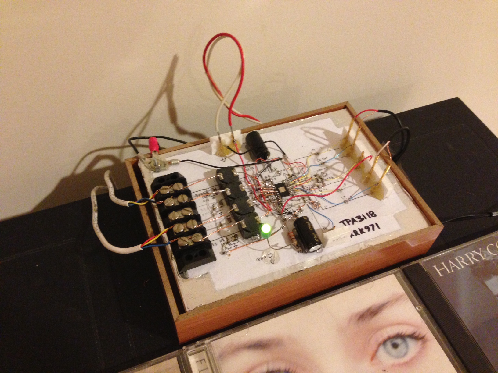
You guys are poo poo'ing this big thru hole board based on the fact that the traces are long and components are big. I am not so sure it makes a big difference. Have you actually heard what this board sounds like before relegating it to the dustheaps of poor sounding designs? I only say this because if you recall I was one of the first to build a tpa3118d2 dead bug style with point to point wiring. I used small SMT components but it was far from an ideal layout and it sounded great. I think it is important to keep the leads between the chip and the inductor as short as possible and keep the power supply bypass caps as close to the chip as possible. But I am not sure if there is detectable effect on SQ if they are a little longer. I would reserve judgement until someone buys one and tests it and listens to it.
Here is the dead bug amp
Here is the dead bug amp
Last edited:
You guys are poo poo'ing this big thru hole board based on the fact that the traces are long and components are big. I am not so sure it makes a big difference. Have you actually heard what this board sounds like before relegating it to the dustheaps of poor sounding designs? I only say this because if you recall I was one of the first to build a tpa3118d2 dead bug style with point to point wiring. I used small SMT components but it was far from an ideal layout and it sounded great. I think it is important to keep the leads between the chip and the inductor as short as possible and keep the power supply bypass caps as close to the chip as possible. But I am not sure if there is detectable effect on SQ if they are a little longer. I would reserve judgement until someone buys one and tests it and listens to it.
Here is the dead bug amp
xrk,
Thank you for bringing this up. After I made my last post, I recalled your creation (the dead bug) which has a lot of long leads, and I did not recall you complained.
By the way, does anyone know which website sells this "big" board?
Regards,
You guys are poo poo'ing this big thru hole board based on the fact that the traces are long and components are big. I am not so sure it makes a big difference. Have you actually heard what this board sounds like before relegating it to the dustheaps of poor sounding designs? I only say this because if you recall I was one of the first to build a tpa3118d2 dead bug style with point to point wiring. I used small SMT components but it was far from an ideal layout and it sounded great. I think it is important to keep the leads between the chip and the inductor as short as possible and keep the power supply bypass caps as close to the chip as possible. But I am not sure if there is detectable effect on SQ if they are a little longer. I would reserve judgement until someone buys one and tests it and listens to it.
Here is the dead bug amp
With this board there are way too many problems summing up
+ Freaking long tracks
+ Electrolytic caps put on vertical with ridiculous long legs
+ Filling empty space with copper is not always a good idea.
+ Distance between critical components is much bigger than the recommended by TI.
+ Through hole components on a poor designed PCB.
I understand as I usually don't like to prejudge.
Unfortunately with this board there are too many things done wrong that I can't really find a single reason for this board sound better than the other designs.
But I am just a newbie and maybe I am missing something in between the lines...
Please, point out atleast one reason for this board to sound better than the other TPA3116 designs ?
[]'s
Last edited:
- Home
- Amplifiers
- Class D
- TPA3116D2 Amp