Hello! I'm very new to the DIY audio scene and have been thinking of building my own Class D amplifier based on pre-built boards.
I was wondering if a toroidal transformer is beneficial for a dual TPA3116D2 board? (100W+100W)
I've been putting together a parts list for it but I can't find an easy enough "short list" of main components I should get, its mostly just more high end stuff.
Does anyone have nice guidance on this? Like a post for beginners or, build guides for cheaper stuff with a run-down of components one should get? Or where I should make a post with my parts to get second opinions on them, see if I'm missing something and maybe even get some tips on getting started?
Thank you!
Greetings to all, in the holes 2 Panasonic FM 1000uF 35v, C6 and C9 are input capacitors and I put Panasonic ECWFE 2,2uF 450v interchangeable. I can't find the function and value of the other components to modify Zobel filter. The gain is quite low, I have to identify the resistance to try to raise the gain a little. Anyone familiar with this board can answer, thank you.
R2/R3 sets the gain of the amp. I think they are 100k/20K on your board. That makes for 26dB gain. Check page 14 of datasheet. You have options for 20dB (lower than now), 26dB which you have now, and louder for 32dB and 36dB. For 32dB you need R2 100K so you don't change that, and R3 39K. So you only replace R3 with 39K for extra 6dB. If you want to go for max 36dB you replace R2 with 75K and R3 with 47K. But input impedance decreases to 9K from 30K which you now have. So you need to up the value of input capacitors C6/C9 to 3.3uF/4.7uF so you don't loose any bass.
Check schematic from page 26 from datasheet, your amp should be the one in the upper part of the schematic. Check the pin numbers and follow the traces to find the parts you want to replace.
Keep in mind that this small board does not have any output filter. I don't see any inductors. They are the 10uH value in the datasheet schematic, with 680nF capacitors to ground. Your board completely misses that, and I wouldn't use it like this. Replacing the input capacitors with same value does almost nothing quality, even if you use 100$ capacitors since you don't have an output filter. That is the best improvement you can do to this board.
Has anyone used the Wuzhi amp, this one?
https://www.amazon.com/Bluetooth-Au...=1&keywords=wuzhi+2x100&qid=1603813141&sr=8-1
I have two of them, and according to the instructions, bluetooth should disable automatically when you plug in a 3.5mm input to the AUX. This does not happen on mine. I have Chromecast Audio connected to both of them (two CCA, two amps). And they still show up when I look for bluetooth devices.
The issue here is that they require no password to connect, which means anyone can connect to them and blast music at high volume if they want.
This is not ideal.
Any idea on how to disable bluetooth?
I think they mean the audio from the bluetooth stops and you get audio from the AUX, into the amp/speakers, when you connect the AUX line. It automatically detects the AUX signal, but I don't think the bluetooth turns off.
Hello! I'm very new to the DIY audio scene and have been thinking of building my own Class D amplifier based on pre-built boards.
I was wondering if a toroidal transformer is beneficial for a dual TPA3116D2 board? (100W+100W)
I've been putting together a parts list for it but I can't find an easy enough "short list" of main components I should get, its mostly just more high end stuff.
Does anyone have nice guidance on this? Like a post for beginners or, build guides for cheaper stuff with a run-down of components one should get? Or where I should make a post with my parts to get second opinions on them, see if I'm missing something and maybe even get some tips on getting started?
Thank you!
Class D amps work fine with switchmode power supplies. A transformer will not be as efficient, and will cost you more once you factor in the other needed parts for the power supply.
.
Does anyone have nice guidance on this? Like a post for beginners or, build guides for cheaper stuff with a run-down of components one should get? Or where I should make a post with my parts to get second opinions on them, see if I'm missing something and maybe even get some tips on getting started?
Thank you!
I’ve been ordering bits to build a pair of 2x100w amps for when I get home.
This is the board I’ve settled on.
Amp KYYSLB DC12 24V High Power 100W*2 TPA3116D2 Digital Power Amplifier Board XH M590 Home Audio Amplifier Board 2~8 Ohms|Amplifier| - AliExpress
I’ll be coupling this with an ne5532 buffer, a meanwell epp-200-24 power supply and a +/- 15v dc-dc converter. I’ll be reducing the gain on the board and replacing a few components, but it should be a good place to start.
rockville apm8 studio monitors
i,ve read your post,good for you!i have rockville apm8 studio monitors and went through them,i have no power to them,fuse is good,eveything else looks good,although there is a ferrite bead missing,burnt and i have no way of getting the schematics to replace the ferrite bead,is there a way to get that info,is there a standard bead to replace thisand how do i find the value of it without applying power to it?
i,ve read your post,good for you!i have rockville apm8 studio monitors and went through them,i have no power to them,fuse is good,eveything else looks good,although there is a ferrite bead missing,burnt and i have no way of getting the schematics to replace the ferrite bead,is there a way to get that info,is there a standard bead to replace thisand how do i find the value of it without applying power to it?
i have a rockville apm8 studio monitor with no power not under warrantee,and power fuse works,yet there is a ferrite bead burnt andi have no way of getting the schematics to get the value of the bead,no technicians around,is there a way to get the value of this with a anaogue meter or without a meter?arethey standard in use or do they have different values?any help,much appreciated!
I have a Bluetooth module identical to that referenced here:
Is this bridgeable?
I'd like to use it to get audio signal to one of my TPA3116 amp boards, but have two concerns:
1. I note that the BT module outputs are amplified. Should I attenuate the output signal to reduce it to line level (if so, how?) or can I just ensure that input volume is kept fairly low?
2. There is a warning as follows:
This product has dual 5W power amplifier circuit. It can not be used in addition to the power amplifier. The output of two amplifiers can not be connected in parallel or connected to the negative electrode, otherwise the power amplifier chip will be damaged.
I cannot decide whether this warns against connecting this module's output to another (TPA3116 or other) amplifier's input or not.
Last edited:
Hi Erik,
It is possible as such. You should use only one of the NS4165 output lines, put a capacitor in series with that output such that the DC-level to ground is eliminated, use a resistive voltage divider on the other side of that capacitor (such that the signal level is reduced) and put a filter capacitor across the output (for low-pass filtering).
Understandable?
Thanks Faux French, for your detailed explanation. I was hoping for a simpler solution but understand the reasons for the modifications. Would this result in a mono signal, so the procedure would have to be repeated on the other NS4165 to achieve a stereo signal?
Given the fact that these BT modules in general are fairly cheap, I think I would rather use a more suitable receiver and keep this one for a later project.
Given the fact that these BT modules in general are fairly cheap, I think I would rather use a more suitable receiver and keep this one for a later project.
IMO it was meant one line for every channel.
Nevertheless you are right that it would be better to get a BT module with a regular line-level output, without the class D amp. Some of the modules have balanced outputs, I would really recommend to consider using the balanced connection to your amp. Some people here have experienced ground loop problems when connecting the BT module powered by the same PSU, even if it was on the same PCB. However, the balanced connection would rule out a volume control via a 2gang potentiometer...
Nevertheless you are right that it would be better to get a BT module with a regular line-level output, without the class D amp. Some of the modules have balanced outputs, I would really recommend to consider using the balanced connection to your amp. Some people here have experienced ground loop problems when connecting the BT module powered by the same PSU, even if it was on the same PCB. However, the balanced connection would rule out a volume control via a 2gang potentiometer...
Thanks phofman for your comments re the ground loop - I've had issues with that before and for sure balanced connections should be the default for these amps, where practical.
Hey everyone!
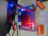
So, after a while using the simple 3116 board I was before, I decided to gift myself a "better one".
Well, while this one does look better (for not much value), there were definitely more issues than the simple board I had before.
After searching, I found out the board I currently own is a version of the XH-M543, mine doesn't have the screws for the heatsink.
Gladly, I found CyberPit's modifications for another similar version of this board and have attempted some of them. That is bypassing the pre-amp and that has fixed the standby hiss and even decreased a bit of the humming noise created by my bluetooth module.
I also followed the Board guide in which suggested 4.7uF capacitors for the Input signal (They're really big, 250V ones...I thought they'd be smaller since I can't really get good quality components without breaking the bank where I live)
Now, I have a few questions regarding this (I am a beginner in electronics):
I noticed that, after the changes I've made the sound became "warm". It's not bad, there is currently little to no distortion even at full volume, but it feels like the bass in not very present. Lower frequencies are finally playing now, but punch bass (and the lower frequencies) are a bit weak.
I have some other capacitors in which are the same values recommended in the board guide. I know they're not high quality caps...
Would it be beneficial to change the board Input DC caps for the ones I got? If yes, which one of them?
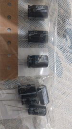
I have 4 of each:
- 470uF 35V from Chong
- 2200uF 25V from Jwco
This board has 6 330uF 35V metal SMD caps, and since I only own 4 of each above, would I be able to just add 4 (of one of the values) and remove 2 of the current 330uF, leaving those points without it? Or is there any other way around I could improve this?
I also plan on adding the mute circuit he made in the future, as the popping is really loud...
So, after a while using the simple 3116 board I was before, I decided to gift myself a "better one".
Well, while this one does look better (for not much value), there were definitely more issues than the simple board I had before.
After searching, I found out the board I currently own is a version of the XH-M543, mine doesn't have the screws for the heatsink.
Gladly, I found CyberPit's modifications for another similar version of this board and have attempted some of them. That is bypassing the pre-amp and that has fixed the standby hiss and even decreased a bit of the humming noise created by my bluetooth module.
I also followed the Board guide in which suggested 4.7uF capacitors for the Input signal (They're really big, 250V ones...I thought they'd be smaller since I can't really get good quality components without breaking the bank where I live)
Now, I have a few questions regarding this (I am a beginner in electronics):
I noticed that, after the changes I've made the sound became "warm". It's not bad, there is currently little to no distortion even at full volume, but it feels like the bass in not very present. Lower frequencies are finally playing now, but punch bass (and the lower frequencies) are a bit weak.
I have some other capacitors in which are the same values recommended in the board guide. I know they're not high quality caps...
Would it be beneficial to change the board Input DC caps for the ones I got? If yes, which one of them?
I have 4 of each:
- 470uF 35V from Chong
- 2200uF 25V from Jwco
This board has 6 330uF 35V metal SMD caps, and since I only own 4 of each above, would I be able to just add 4 (of one of the values) and remove 2 of the current 330uF, leaving those points without it? Or is there any other way around I could improve this?
I also plan on adding the mute circuit he made in the future, as the popping is really loud...
Attachments
With modern sources you should not have use for the opamp. I removed all related to that from my board. I'd use the lowest gain setting of the tpa3116 and use a decent source that you control the volume from.
That opamp circuit might mess with the quality of the signal that would explain the bass issues.
That opamp circuit might mess with the quality of the signal that would explain the bass issues.
With modern sources you should not have use for the opamp. I removed all related to that from my board. I'd use the lowest gain setting of the tpa3116 and use a decent source that you control the volume from.
That opamp circuit might mess with the quality of the signal that would explain the bass issues.
I think I've done that with CyberPit's mod:
TPA3116D2 2 channel Amprefire Modification
(See his modified schematic)
Either way, I think it might have had to do with either chip burn in or something, after a few good hours of listening the bass got a bit more punchy, took a long while though.
I kinda wish I had the components to make the muting circuit, it's horrible whenever I have to turn off/on the amp, would be good I could just remove the speakers though haha
Anyways thanks! Would you have some opinions on the capacitors I mentioned?
Yes, the turn on thump can be horrible on some of these modules. I just have the speaker ground disconnected on one mono module while it's switched on and then connect it seconds later. I know these are supposed to have a speaker load but have no idea how long they can go without one before it becomes an issue.
I was going to try a 4R resistor on the speaker +ve to ground at startup and then switch over to the speaker.
Other modules such as the Danzz design blue / black are fine on startup and shutdown so looks like it's all down to implementation.
I was going to try a 4R resistor on the speaker +ve to ground at startup and then switch over to the speaker.
Other modules such as the Danzz design blue / black are fine on startup and shutdown so looks like it's all down to implementation.
I do not have major issues at turn-ON or -OFF with any of my TPA3116 amplifiers. Make sure that you always turn the TPA3116 amplifier ON as the last and always OFF as the first. I guess the need for a load is particular at start-up where a resonant ringing may be generated. If you need to disconnect the speakers at any moment where the TPA3116 chip is under power, try keeping an 100Ohm/5W resistor connected across each output at all times. It reduces the risk of a serious resonance.
Last edited:
Let us do the math. Suppose L=10uH and C=1uF
Fres = 1/2*pi*sqrt(L*C) = 1MHz/2*pi*sqrt(10) = 50kHz.
The resistor for critical damping is
R = sqrt(L/C) =3.2 Ohms.
These numbers tell us:
1.Damping with 100R will make no significant diffence
2. For perfect critical damping a resistor of 3.2 Ohms is required - and this is a real resistor measured at Fres, i.e. at 50kHz. In reality no speaker has such a low and real impedance at 50kHz - and that means the speaker does not contribute to significant damping at all. You may omit it as well, no harm to be expected.
Another conclusion is that these frequency plots published by TI and other certainly use low inductance dummy loads achieving their frequency plots at rated impedance under laboratory conditions.
After all it would be closer to reality to measure unloaded output - which is avoided for obvious reasons.
Last edited:
Following the numbers the proposed snubbers are either without effect or will burn in case of resonance excitation.
All this can be avoided by a proper post-feedback circuit.
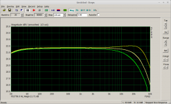
The resulting frequency response of my approach with 5R, 10R and no load, without any snubbers is documented at this plot.
All this can be avoided by a proper post-feedback circuit.
The resulting frequency response of my approach with 5R, 10R and no load, without any snubbers is documented at this plot.
Attachments
Good work bucks bunny. My point is that the stimulation is not a steady signal but rather a "one-off" type, like if you expose the LC circuit to a voltage step. As you seem very skilled in simulation, try comparing the time-dependent voltage across the capacitor for a series-resonant circuit with and without 100 Ohm across the capacitor. Try eventually with a 12V step.
- Home
- Amplifiers
- Class D
- TPA3116D2 Amp