Hope you understood my sketch, looks kinda shitty tbh.
Yeah i think i got it. The drawback is that i will probably loose the volume pot
But what is with L-in(-) and R-in(-) is that always grounded that it does not need to be bypassed?
Is it possible to estimate the size of the caps? I've here two WIMA MKS4 foil caps with 1µf. So im wondering if these are big enough to replace the ceramic caps i put the switch onto. Or makes it more sense to replace with them the even bigger ones at the bass pot?
and take the aux signal before the input caps (C2/C3), you remove those completely
how big are these input caps? Ok when i put the signal directly to the switch / big caps they are useless to be replaced by some foil caps but just in case how big these should be?
The datasheet of TPA3116D2DAD EVALUATION BOARD says 1µf for input caps but that probably means directly before the TPA3116? So does the signal before bluetooth "stage" and the signal before opamp "stage" all need such big caps or could the caps right after aux be smaller ones (e.g. 0.33µf)?
beside the two WIMA MKS4 caps i also have a bunch of 2A105J (metallized polyester film caps with 1µf 230V) would it make sense to replace the ceramic caps on bass poti with these? (but definatly would need some wireing because of the size).
I did it behave like i would expect from the datasheets of BT chip and NE5532Do test all the connections.

But i don't understand where the - of the left/right audio signal is comming from...is that just grounded?
Last edited:
I had some static noise from my fosi audio TDA7498e because it's an aluminium volume knob
The static noise is not because of the aluminium knob, it's because the volume pot is not grounded correctly.
Fitting a plastic knob will not fix the root cause, it will just cover up the problem.
Yeah i think i got it. The drawback is that i will probably loose the volume pot
But what is with L-in(-) and R-in(-) is that always grounded that it does not need to be bypassed?
Is it possible to estimate the size of the caps? I've here two WIMA MKS4 foil caps with 1µf. So im wondering if these are big enough to replace the ceramic caps i put the switch onto. Or makes it more sense to replace with them the even bigger ones at the bass pot?
how big are these input caps? Ok when i put the signal directly to the switch / big caps they are useless to be replaced by some foil caps but just in case how big these should be?
The datasheet of TPA3116D2DAD EVALUATION BOARD says 1µf for input caps but that probably means directly before the TPA3116? So does the signal before bluetooth "stage" and the signal before opamp "stage" all need such big caps or could the caps right after aux be smaller ones (e.g. 0.33µf)?
beside the two WIMA MKS4 caps i also have a bunch of 2A105J (metallized polyester film caps with 1µf 230V) would it make sense to replace the ceramic caps on bass poti with these? (but definatly would need some wireing because of the size).
I did it behave like i would expect from the datasheets of BT chip and NE5532
View attachment 870675
But i don't understand where the - of the left/right audio signal is comming from...is that just grounded?
Depends where the volume pot is implemented in the circuit. I don't think it's before the bt chip. You could always check. I think you should still have the volume control after you implement what I described.
You have an audio jack aux input, that is not balanced, it's single ended. That means that the input signal - is at ground level. So you only need to route left/right positive inputs.
I have no idea on the aux input caps. It depends on the bt chip, and I don't see any in its schematics. I presume it goes to the ADC lines. Depends on the input impedance which is not specified. Based on the input impedance you choose a capacitance that allows for 20Hz to pass without attenuation. You could always measure the aux input ones, but in this case what matters is that the capacitance value to not be too low. If it's higher then that's no problem.
Looking at sizes I'd say the two larger smd caps that are between bt chip and opamp are higher value than the aux input ones, so you can safely implement the switch the way I described. You desolder the two large ones and solder them upright on the lower pads, and use the top connection that's in the air as signal input to the opamps, from the two middle pins of the switch.
I think you could use the 1uF wima caps. Do you have a multimeter? Some of them have a capacitance measuring function. If not I suggest you get one capable of measuring capacitance if you wanna tinker with audio stuff. It's very useful.
Ideally you'd use polypropylene caps in the signal path. If you have polyester then that will work fine instead of the ceramic ones. Wima mks is polyester and mkp is polypropylene.
Looking at the first opamp, I see two resistors that look suspiciously close to the input lines, and seem to be grounded on one side, so I presume those set the input impedance of the opamp. At 473 value that's 47K. Running a simulation with a variable input capacitor (100n to 1uF) looks like this:

The lowest trace is 100nF and highest is 1uF, so you can safely use a 1uF value for 47K input impedance. At least I think that's how the resistors are used.
The static noise is not because of the aluminium knob, it's because the volume pot is not grounded correctly.
Fitting a plastic knob will not fix the root cause, it will just cover up the problem.
I didn't notice anything when using my knob from my tube buffer
You have an audio jack aux input, that is not balanced, it's single ended. That means that the input signal - is at ground level. So you only need to route left/right positive inputs.
a ok, just incase i'm not bypassing the aux from the back but adding a second one on the side (to have 2 aux inputs i can switch between) can i solder the left/right - to any ground pad nearby i find?
https://www.ti.com/lit/ug/slou336b/slou336b.pdf i think says 1µf on each side to ground so i can put a 2µf cap to any groundpad i find and solder the - to that?
I think you could use the 1uF wima caps. Do you have a multimeter? Some of them have a capacitance measuring function. If not I suggest you get one capable of measuring capacitance if you wanna tinker with audio stuff. It's very useful.
Ideally you'd use polypropylene caps in the signal path. If you have polyester then that will work fine instead of the ceramic ones. Wima mks is polyester and mkp is polypropylene.
unfortunately my multimeter has no capacity measurement but yeah maybe time to upgrade that (beside some new tips for my soldering irons)
I replaced the 2 ceramic caps with the wima mks4. Not sure yet if it sound different.
I did not added the switch yet (cause just have single switches) but might going for some jumpers for now when it is clear if i can use a second aux socket.
You can add another jack and route that to a double throw double pole switch (DPDT). You can use any ground pad/connection for the negative.
Since you have two channels, you need to add two capacitors, one for each channel negative input to ground (for tpa3116 chip).
But I would remove the heatsink (twist it sideways so you don't risk ripping the chip off the pcb). Then check if there's the two capacitors going to ground, from left/right negative inputs. They might be hidden under the heatsink.
gasolin75 You mentioned in a few threads about your problem with noise when adjusting the volume. Try the following 2 things.
remove the volume knob and put some nail polish on the shaft. Get a nylon set screw for the knob.
remove the front panel and connect a wire to all of the control shafts and then connect that wire to ground. Before putting the front panel back on check to make sure all is ok.
remove the volume knob and put some nail polish on the shaft. Get a nylon set screw for the knob.
remove the front panel and connect a wire to all of the control shafts and then connect that wire to ground. Before putting the front panel back on check to make sure all is ok.
what ground on,in the amp ?
Im asking since i don't know what ground i should connect the wire too
If you don't know it i bought a new amp that doesn't have the problem (according to fosi audio)
Im asking since i don't know what ground i should connect the wire too
If you don't know it i bought a new amp that doesn't have the problem (according to fosi audio)
Last edited:

on the top left of your photo there is an input ground clearly labeled. With a meter check for 0 ohms between the input ground and the area you circled.
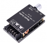
I bought this module off Aliexpress.
The bluetooth is, as I expected, unusable because it degrades the sound quality a whole lot. I can live with that since I don't plan on using it anyway.
The volume pot however has a problem that I do wish to get rid off.
The pot is one with an integrated power switch. I think they did that to tackle the startup plop problem.
However I've noticed that turning the knob creates a DC offset. I see the speaker cone move outward or inward as I turn the knob left or right. The faster I turn, the more this problem occurs. As if turning the pot somehow generates a voltage on the signal line.
I do not wish to damage my speaker drivers, so I want to find the root of this problem. Is it a faulty pot, or is it a faulty amplifier design?
If anyone has an idea what could cause this phenomenon, please let me know.
Attachments
I bought this module off Aliexpress.
The bluetooth is, as I expected, unusable because it degrades the sound quality a whole lot. I can live with that since I don't plan on using it anyway.
The volume pot however has a problem that I do wish to get rid off.
The pot is one with an integrated power switch. I think they did that to tackle the startup plop problem.
However I've noticed that turning the knob creates a DC offset. I see the speaker cone move outward or inward as I turn the knob left or right. The faster I turn, the more this problem occurs. As if turning the pot somehow generates a voltage on the signal line.
I do not wish to damage my speaker drivers, so I want to find the root of this problem. Is it a faulty pot, or is it a faulty amplifier design?
If anyone has an idea what could cause this phenomenon, please let me know.
Same as the nobsound, douk audio amp Mini HiFi Bluetooth 5.0 Digital Power Amplifier Stereo Audio Amp Board+Case 100W
Remember to watch the part just when he has turned on the amp before theres any music TPA3116 amp board 2x50W (Unboxing, Assembly & Sound Test) - YouTube
Yes, only I have the ZK-1002 version, which is dual chip 2x 100w.
The video shows exactly the issue I have. I wonder what could could be the cause and how it can be avoided.
My plan is to add a volume pot before the aux in, and completely forget about the bluetooth. But if there is a better solution I would like to know.
The video shows exactly the issue I have. I wonder what could could be the cause and how it can be avoided.
My plan is to add a volume pot before the aux in, and completely forget about the bluetooth. But if there is a better solution I would like to know.
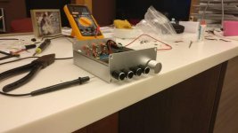
This is a popular tpa3116d2 2.1 Amp. I ve out it in a anodized aluminum box with plastic pot caps and I get noise when changing the volume. I only get the noise when there is signal going through, if it doesn't its silent. At first I thought it was the common cracking noise pots make when they are dirty but its relative new and as I said it only does it when it's playing music. The psu is a generic laptop brick. I don't understand why it does this is it a ground problem? In the pictures you can see that the pots touch the frame which does not have isolation feet and it sits on a wooden table
Attachments

Yes, only I have the ZK-1002 version, which is dual chip 2x 100w.
The video shows exactly the issue I have. I wonder what could could be the cause and how it can be avoided.
My plan is to add a volume pot before the aux in, and completely forget about the bluetooth. But if there is a better solution I would like to know.
Tube buffer ?
FX Audio 6j1 tube preamp - a $31 wonder | Audiokarma Home Audio Stereo Discussion Forums
I wouldn't waste my time with these tube buffers. It has a 12V power supply. The tubes need to be ran at 200-300V to be in the linear region, and need some current. The power supply would be pretty big for such a setup.
Even if it looks like it's working, they are far from any decent operating point. Some of them are only providing some filament voltage but have an opamp bypassing them.
I don't want to be a downer but they are pretty crap for a tube buffer/preamp.
Even if it looks like it's working, they are far from any decent operating point. Some of them are only providing some filament voltage but have an opamp bypassing them.
I don't want to be a downer but they are pretty crap for a tube buffer/preamp.
I wouldn't waste my time with these tube buffers. It has a 12V power supply. The tubes need to be ran at 200-300V to be in the linear region, and need some current. The power supply would be pretty big for such a setup.
Even if it looks like it's working, they are far from any decent operating point. Some of them are only providing some filament voltage but have an opamp bypassing them.
I don't want to be a downer but they are pretty crap for a tube buffer/preamp.
Did you just read a $31 wonder and thought something that cheap can't make a difference or did you actually read a few pages ?
Last edited:
- Home
- Amplifiers
- Class D
- TPA3116D2 Amp