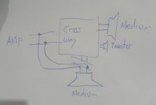
So could this be the solution?
Instead of drive both medium chassis from the crossway I can plug one direct to the amps output?
But I have also the problem when I drive only the sub chassis. This is direct connected to the amps output with no crossway or something like that.
So I could be the max output current limitaion of the amp.
Because same configuration and no problems with TAS5611 amplifier.
Attachments
So could this be the solution?
Instead of drive both medium chassis from the crossway I can plug one direct to the amps output?
But I have also the problem when I drive only the sub chassis. This is direct connected to the amps output with no crossway or something like that.
So I could be the max output current limitaion of the amp.
Because same configuration and no problems with TAS5611 amplifier.
What you propose should be much better.
If possible, try for a moment to connect one mid-tone driver directly (without cross-over) to each of the outputs of the TPA3116. Add the bass driver directly on the sub-channel. Any cut-outs?
A TPA3116 and a TAS5611 can react very differently to a partly insufficient loading.
You can leave a class AB amplifier playing without a load. For a class D amplifier, no load may destroy the amplifier.
You have two problems. First, load the D-amp in a way that does not trigger it´s protection or destroy it.
Second, keep the undesired (sub driver) or harmfull (midd/high) frequency away from the speakers.
You can not use the midd high driver without x-over, as it will distort and burn at relative low level.
If you have a small full range box you want to use as a satellite, you can reduce the value of the amps input capacitor until the frequency response drops with 6dB/oct.
This is the same as a single capacitor in front of the driver.
With the sub driver, you don´t want it to play high frequncy which will break up the cones linear travel and produce distortion / coloration to the sound.
You may, the same way as with the high´s, just use a capacitor to ground. It will cancel the high frequency out, before it enters the amp for the sub driver.
This is a first order active x-over high pass and low pass. It is a pitty that 6dB/oct are a very tame down slope.
If you want to go that far, my advice is: Get a used car sub woofer active x-over from eBay. Feed it through a simple 15V regulator and you are done. You will have 12-24 dB/oct slope, adjustment of volume and in most cases, no hum or noise, as these are well decoupled for the noisy car voltage. Also, sound wise, this will be the best you can do, as even cheap active x-overs offer decend sound quality.
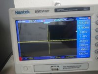
So I made mesurement one channel medium/tweeter.
the peak is between two shutdowns 🙂
If it is still current with your 100mOhm shunt resistor it looks dramatic.
I looked again at the MP4 you posted some days ago to know the amplifier board better.
I did not find exactly the same board on the Internet. One thing entered my mind as a concern: your output filter chokes. If they are 10uH they will max. take 5A peak, if they are 33uH max. 3A peak (I cannot see the value from the video). You have rather low impedance speakers and music with strong bass. With that kind of music and a good sound level your output current may naturally get to many Amperes. If you reach the saturation level of the chokes, the chokes become short-circuits and the amplifier output lines look straight into the output filter capacitors (some 0.68uF). If so, your carrier frequency (400KHz) is short-circuited and your amplifier will shut down. Anything wrong in this line of thinking? Do we simply deal with saturated filter chokes?
I did not find exactly the same board on the Internet. One thing entered my mind as a concern: your output filter chokes. If they are 10uH they will max. take 5A peak, if they are 33uH max. 3A peak (I cannot see the value from the video). You have rather low impedance speakers and music with strong bass. With that kind of music and a good sound level your output current may naturally get to many Amperes. If you reach the saturation level of the chokes, the chokes become short-circuits and the amplifier output lines look straight into the output filter capacitors (some 0.68uF). If so, your carrier frequency (400KHz) is short-circuited and your amplifier will shut down. Anything wrong in this line of thinking? Do we simply deal with saturated filter chokes?

please watch out! the GND is Earth grounded in scope! so do not use it like a DMM.
You are right, not particularly pretty.
I assume what we see is a variable frequency signal on the sub-channel with so powerful a signal that the amplifier saturates. Correct?
Could we please have the same output with 100Hz fixed frequency and the signal reduced so there is no saturation?
The HK chokes look better.
I assume what we see is a variable frequency signal on the sub-channel with so powerful a signal that the amplifier saturates. Correct?
Could we please have the same output with 100Hz fixed frequency and the signal reduced so there is no saturation?
The HK chokes look better.
Uhm, I broke the trace of R2 tinkering with other things, trough hole components soldered to smd into so little space is a nightmare. I can't find another spot to solder to. In the photo is the 473 resistor under the green circled one.
Maybe I'm ready to buy a better pcb...

Maybe I'm ready to buy a better pcb...
Working with SMD PCBs is a challenge and when the PCB-traces and pads start getting ruined it is a nightmare to repair. At least you have seen that noise problems can be solved without much extra investment.Uhm, I broke the trace of R2 tinkering with other things, trough hole components soldered to smd into so little space is a nightmare. I can't find another spot to solder to. In the photo is the 473 resistor under the green circled one.
Maybe I'm ready to buy a better pcb...
You now have a board with poor PCB traces, without an output filter and with some "pop"-noise. Only the more stubborn persons would insist on continuing.
For the next board, ask in the TPA3116D2 thread which to buy. There are many members with extensive experience.
Good luck!
NB: Keep this board for when you may need a component for replacement in the future.
Last edited:
Working with SMD PCBs is a challenge and when the PCB-traces and pads start getting ruined it is a nightmare to repair. At least you have seen that noise problems can be solved without much extra investment.
You now have a board with poor PCB traces, without an output filter and with some "pop"-noise. Only the more stubborn persons would insist on continuing.
For the next board, ask in the TPA3116D2 thread which to buy. There are many members with extensive experience.
Good luck!
NB: Keep this board for when you may need a component for replacement in the future.
Thanks for the help!
Hot air rework station is an absolute necessity for this kind of repair work. And set properly it will not damage anything as the air is below soldering iron tip temperatures even. Oh and a jar of flux and ceramic tipped tweezers too...Working with SMD PCBs is a challenge and when the PCB-traces and pads start getting ruined it is a nightmare to repair.
Hot air rework station is an absolute necessity for this kind of repair work. And set properly it will not damage anything as the air is below soldering iron tip temperatures even. Oh and a jar of flux and ceramic tipped tweezers too...
Well, I have evertithing I need and I'm not new to this kind of things, but my problem was differend, I overturned the third hand on the pcd and it did hit the resistor who was a little tall and already soldered on the smd spot, ripping them off 🙁
FauxFrench
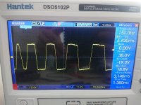
I made a video with 100Hz sinewave.
Many thanks, Hansueli,
It shows that this amplifier channel works. Clipping a bit above 15V (a bit early with a 19V supply or you use the battery?) and not very pretty clipping (not a flat horizontal level) but at least the amplifier does not shut down. The amplitude is varying but I believe to see as a reflection in the scope-screen that you are turning the potentiometer?
If you put an Ohm-meter on the speaker you used for this channel, what value do you get?
- Home
- Amplifiers
- Class D
- TPA3116D2 Amp