Regarding the burnt channel - make sure not to run the amp without output load (speaker or resistor). Or install protection diodes to the outputs as described by https://www.diyaudio.com/forums/class-d/237086-tpa3116d2-amp.html#post3528020
Hi StevieF,
Your TPA3118 is PBTL coupled, as you already know, so your Veff is 24V for the following calculations.
How to choose the power supply for your class D amplifier module.
Typically less experienced DIYs repeatedly ask about this issue. It is not particularly difficult but requires knowledge of Ohms Law, the functioning of a class D amplifier and a Buck (step-down) power converter and some general electronic overview.
Only one channel (mono) will be considered. If you need two amplifiers (stereo) to operate from the same power supply, you simply double the current capability of the power supply such that also the power rating is doubled.
Important parameters
For deciding the right power supply, the maximum (operational) power supply voltage and the maximum output current (where the over-current protection is activated) of the amplifier need to be known (see the specifications or the chip datasheet). You also need to know if the amplifier operates from a single supply voltage or two symmetrical (+ and -) supply voltages. Next, you have to design for optimum operation with 8 Ohm or 4 Ohm speakers, eventually 2 Ohm speakers for automotive use.
The effective operating voltage
The effective operating voltage (Veff) is the voltage the amplifier can use to generate a sine half-wave.
For class D amplifiers operating in BTL configuration from a single supply voltage it is the single rail-to-ground voltage.
For class D amplifiers operating in SE mode with one speaker terminal connected to ground and a symmetrical supply voltage it is the voltage from one rail to ground.
For class D amplifiers operating in BTL mode with a symmetrical supply voltage it is the voltage from one rail to the other rail, thus, double the voltage from one rail to ground.
This effective operating voltage indicates the maximum peak voltage the amplifier can generate for a sine half-wave. From a sine half-wave peak value to the rms value, the factor 1.41 applies. The rms value is found by dividing the peak value with 1.41.
Though the theoretical conversion factor is 1.41, it is suggested to use the factor of 1.5 when calculating the rms value of a sine half-wave that can be generated from an effective operating voltage (Veff). Then, some output switch drop is taken into account.
As an example, for a BTL-coupled amplifier that can handle a single supply voltage of 36V, the rms value of the sine half-wave that can be generated by the amplifier is 36Veff/1.5=24Vrms.
With the rms voltage of the sine wave signal, the power in a load can be calculated using the expression Vrms*Vrms/Rload. Using the values from the example above: 24Vrms x 24Vrms / 8 Ohm = 72W. Or, for a 4 Ohm load: 24Vrms x 24Vrms / 4 Ohm = 144W.
This way we can calculate how much AC signal power it is possible for the amplifier to generate in the load PROVIDED the amplifier can stand the resulting current.
The maximum current for an amplifier output
This value is more difficult to find in a chip datasheet. Sometimes it is specified as the (peak) current the amplifier can handle at an output, sometimes as the output current where the (over-) current limiter is invoked. Some datasheets are not clear about if the chip can stand the maximum (peak) current on more outputs at the same time.
When we have calculated the maximum output power the supply voltage will allow, we have to compare the resulting current against the maximum current for the amplifier chip. To calculate the maximum peak output current, we simply divide Veff with the load impedance. Veff / 8 ohm for 8 Ohm load and Veff / 4 Ohm for 4 Ohm load.
Using the values from the example above, the peak current value in 8 Ohm will be 36Veff / 8 Ohm = 4.5 Apeak. In 4 Ohm it will be 36Veff / 4 Ohm = 9 Apeak. Let’s assume the amplifier can handle 6 Apeak at the output(s), operation with 8 Ohm load is fine (max. 4.5Apeak) but operation with 4 Ohm load (max. 9Apeak) will result in over-current at a certain output level.
If we know we will use the amplifier from the example above with 4 Ohm speakers, we need to lower the supply voltage (Veff) such that the maximum current at an amplifier output is not exceeded. Reducing the supply voltage (Veff) to 24V means the peak current in 4 Ohm will be 6A and the amplifier maximum current is not exceeded.
Calculating the power supply capacity
When the maximum output power that is possible with a certain supply voltage has been calculated and the maximum current at the amplifier output has been successfully checked, we need to calculate the power capacity of the power supply.
Here, we use the knowledge that a class D amplifier has an efficiency of typically 90%. To be prudent we use 80%.
The classical way assuming test with a constant amplitude sine-wave: The maximum output power from the amplifier is divided by 0.8 (80%) to take amplifier losses into account. Using the values from the example above, 72W in 8 Ohm requires a power supply of 72W / 0.8 = 90W. In 4 Ohm, 144W / 0.8 = 180W.
The realistic way assuming use with music: The power supply capacity (Watt) calculated above is divided by two. Why? Because music has got a “crest-factor” meaning that no music is demanding full power for long. Actually, most music has long passages with rather quiet sound and short passages with powerful sound. Therefore, it is seen as unrealistic to design the power supply for maximum sound level all the time. Clever and competent people estimate the steady-state power supply need to be half of what is normally needed for the maximum power the amplifier can output. The power line decoupling capacitors are handling the need for short but powerful surge currents.
Using the example above with 72W in 8 Ohm will then require only a 45W power supply (half of 90W).
Can we swap 4 and 8 Ohm loads?
Yes, but with two different results. If the amplifier and power supply are optimized (designed) for a 4 Ohm load, you can always use an 8 Ohm load instead – but, you will only get half the output power. No overload. If the amplifier and power supply are optimized for an 8 Ohm load, you can use a 4 Ohm load instead at lower output levels. But at a certain output level, the higher current demanded by the 4 Ohm load will exceed the current capability of the amplifier and perhaps also power supply such that you have an over-current situation.
Therefore, 8 Ohm speakers are the most versatile if you do not need the extra power.
Last edited:
Thanks alot for the explanation FauxFrench. Highly appreciate your efforts, very well explained.

Regarding the burnt channel - make sure not to run the amp without output load (speaker or resistor). Or install protection diodes to the outputs as described by https://www.diyaudio.com/forums/class-d/237086-tpa3116d2-amp.html#post3528020
As a related question, do the TDA7492 modules also have this problem or can they be powered up without output load?
I do not know, but look at the circuit on page 10 of https://www.st.com/resource/en/datasheet/tda7498e.pdf - the protection diodes are shown.
As a related question, do the TDA7492 modules also have this problem or can they be powered up without output load?
It is a general problem caused by the inductance of the filter choke and the resonance. My TDA7498E amplifier module uses catch-diodes. Similar for my TA2022. NXP shows catch-diodes in their TDA8954 datasheet.
Catch-diodes may be included in the chip design and then they are not needed.
I do not know, but look at the circuit on page 10 of https://www.st.com/resource/en/datasheet/tda7498e.pdf - the protection diodes are shown.
The catch diodes shown in the data sheet do NOT address the no-load issue. This requires diodes that clamp the filter output to the supply rails.
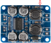
I just managed to strip a cap off the board of my cheap *** PBTL tpa3118. The amp still works but I don't have a proper speaker to test it so I'm not sure if it's affecting the sound or how much. Can someone please help me figure out what it's meant to do and if I can replace it with a through hole one which value would I need? Ceramic or polyester? I can order another one no problem, but it's gonna take a while to get here so I thought I might try to fix it myself if needs to be fixed at all
Thanks
Thanks
Attachments
Checking the schematic in the datasheet looks like that cap is one of the 10nF of the snubber, right? Well, It won't hurt to try that I guess
I just managed to strip a cap off the board of my cheap *** PBTL tpa3118. The amp still works but I don't have a proper speaker to test it so I'm not sure if it's affecting the sound or how much. Can someone please help me figure out what it's meant to do and if I can replace it with a through hole one which value would I need? Ceramic or polyester? I can order another one no problem, but it's gonna take a while to get here so I thought I might try to fix it myself if needs to be fixed at all
Thanks
I measured it & got a reading of 1.5uF. You can use ceramic or polyester through hole in its place.
I measured it & got a reading of 1.5uF. You can use ceramic or polyester through hole in its place.
Damn, I only have electrolytics of that capacity. Thanks Stevie
The catch diodes shown in the data sheet do NOT address the no-load issue. This requires diodes that clamp the filter output to the supply rails.
Thanks for correction, very appreciated. I have seen blown output filters due to no load.
What is the actual purpose of those catch diodes before the filter? Thanks a lot.
That is a good question. I suspect they do not help anything in practice.Thanks for correction, very appreciated. I have seen blown output filters due to no load.
What is the actual purpose of those catch diodes before the filter? Thanks a lot.
Thanks for correction, very appreciated. I have seen blown output filters due to no load.
What is the actual purpose of those catch diodes before the filter? Thanks a lot.
Whenever you switch the current in an inductor, you must ensure the inductor always has a closed circuit for its current. If not, the inductor can very rapidly generate a fly-back voltage and destroy components connected to either end of the inductor. Before the filter, the catch-diodes protect the IC.
Whenever the IC output switches themselves do not clamp the inductor voltage to either of the two supply rails, the clamp-diodes have to take over the current and avoid an over-voltage across the output switches. I can imagine this to be a problem in particular if the output switches are not turned correctly on due to current limitation.
I have had a TDA8954 output destroyed when driving a very lossy filter choke. I guess the current limitation was invoked (it sounded bad at the output) and voltage spikes caused the output stage to burn (permanently shorted), probably through the boot-strap capacitors going to the drive circuit.
The TDA8954 design relied on a snubber circuit that was wrongly implemented. Now I use fast 1A (nominal current) Schottky diodes and a correct snubber and all works well.
Last edited:
There are no MOSFETs without an intrinsic antiparallel body diode. That is why freewheeling diodes in the context mentioned above do not make sense for me.Thanks a lot for explanation. Do the TPAxxxx chips have the clamp diodes integrated?
No, there are no dangereous voltages spikes to be expected,I have had a TDA8954 output destroyed when driving a very lossy filter choke. I guess the current limitation was invoked (it sounded bad at the output) and voltage spikes caused the output stage to burn (permanently shorted), probably through the boot-strap capacitors going to the drive circuit.
but
the "lossy" chokes may have been underrated, i.e. they saturated during operation. In that case inductance drops close to zero, current increased too fast thus internal current limit acts too late - chip is destroyed by over-current, not over-voltage.
For that reason you will find a minimum value of output filter inductance in the data sheets, often 1uH.
As a general rule, the saturation current of output inductor must exceed the max overcurrent trip point of class-d-chip.
No, there are no dangereous voltages spikes to be expected,
but
the "lossy" chokes may have been underrated, i.e. they saturated during operation. In that case inductance drops close to zero, current increased too fast thus internal current limit acts too late - chip is destroyed by over-current, not over-voltage.
For that reason you will find a minimum value of output filter inductance in the data sheets, often 1uH.
As a general rule, the saturation current of output inductor must exceed the max overcurrent trip point of class-d-chip.
The lossy choke I tried was rated at more than 30A. I had no specs on it and the frequency behavior may have been a problem. At least the output sounded really bad.
For many years, power MOSFETs were characterized by an intrinsic slow body diode. Often the MOSFETs were bypassed by fast Schottky diodes to avoid the intrinsic diodes being forward biased. Could that be the purpose of the diodes we find before the filter?
Search on the Internet indicates that the intrinsic body diode problem has not been solved on wafer level. They are still there.
agreed. But you will not find much information about intrinsic body diodes of class-d-amps, if any.
The culprit is that an external clamp diode cannot bypass the very fast turn-off-switching MOSFET due to its wiring inductance.
Last edited:
- Home
- Amplifiers
- Class D
- TPA3116D2 Amp