Sorry, I was wrong and it is explicitly stated not to be conductive. But, it is also advised not to leave it in contact with pins because it is "very slightly" (?!) capacitive. So, use with moderation just like alcohol.
I finally had my 3116 board delivered. The red Sanwu one I was asking about earlier.
In PBTL mode I cannot use 4 set of snubbers like in the pic I posted earlier, using 4 causes the power supply outputs to short themselves I feel because my meanwell psu keeps recycling itself & doesn't turn on properly.
Mine has the heat sink thermally glued to the chip, so I can't change the gain on it like I had on the blue tpa3118 pbtl boards. However, the sound of this red sanwu board is truly excellent without any major component swaps.I'll be ordering one more for backup purposes. i'm feeding it ~21V, sounds very good at that Vin, I get plenty of bass at that point. Overall i'm very pleased with this one, for the price its excellent in sound quality.
The build quality could have been better though, looks like all the cap & connector legs were cut after the soldering process & some solder points needed reflow.
The build quality could have been better though, looks like all the cap & connector legs were cut after the soldering process & some solder points needed reflow.
They are cut with something reminding of a fine saw-blade. It rarely looks nice and the lead ends are bend in different directions if the cutter is not well trimmed.
Well, that board I posted works great! I'm using it on the output of a two-way crossover, that is supposed to have been set for ~75hz, but I goofed on the math and set it to ~51hz with the components I used 
Since the internal low-pass is set so high (~180hz or so) using it after a crossover is likely the best solution, but I'm happy with the performance. The speaker I'm using is definitely the weakest link here, but still performs well. The intention was just to fill in the bottom end of the .53X karlsonator speakers I use, which drop off around ~60-65hz or so, for good all-around music/movies/gaming, and it works well enough for that.
To test it out I listened to about half of the Massive Attack- Mezzanine album, and then watched the Lord of The Rings trilogy over the next few days. I'm very pleased 😎
I'll likely end up either modifying the crossover to the originally intended ~75hz or so crossover point, or simply build another to have a couple options onhand. I need to buy more capacitors before I can build another, however, so I'll mull it over the next few days. The crossover I built is here-
12dB / Octave Linkwitz Riley Crossover
I'm sorry to have to post this but I think buyers should be aware of my experience in the last couple of weeks with Connex, I have sent them emails regarding info of the aux pin-outs on both amp and smps and they just don't reply or they say that my emails go to their spam, their products are good but if you have any problems you are on your own.
I'm sorry to have to post this but I think buyers should be aware of my experience in the last couple of weeks with Connex, I have sent them emails regarding info of the aux pin-outs on both amp and smps and they just don't reply or they say that my emails go to their spam, their products are good but if you have any problems you are on your own.
My impression is that their designs are OK but they definitely have a documentation problem. As you rightfully say, the use of the interface pins is not obvious.
I happened to try to help a forum member with identifying the pin-use on two CxD250-HP (as I recall it) modules he had bought but could find no documentation for. As I recall, this forum member managed to ruin both his two modules before finding the correct use of the pins!
Even today the "Description" for the CxD250-HP states at the end: "Product manual will be available soon". With 8+5 interface pins and as I recall at least two different supply voltage sets, it is not reasonable that it is up to the customer to analyze the circuit and experiment with its use.
We all had to write documentation in the past, that necessity has not become futile.
It is as such possible without working on the chip pins. The difference between BTL (stereo) and PBTL (mono) configuration is described in the datasheet, section 7.4.1.
For the jumpers at the output side, you can make these connections at the PCB pads for the filter chokes.
For the input side, you have to work on the small PCB pads for the input coupling capacitors (SMD I believe). The capacitors should be removed and the PCB pads toward the TPA3116 chip connected to GND. This is a bit more delicate but possible.
Thank you so much for the help, cant believe i didnt see that before. I did the mod today and it worked perfectly.
You dont happen to havet any suggestions on my low pass problem? 🙂
I cannot tell you if you are looking at the right 47K and 68nF (for a Sallen-Key filter there should be two 47K and two 68nF). I do not known this board. If they are the right components, it should be possible to change the filter cut-off frequency to 3.4KHz. Are they SMD components, you may prefer to change only one type of component. If you can change both types, I would use 10K/4.7nF or 4K7/10nF. I prefer circuits with not too high impedance.
Is that your low-pass problem?
Is that your low-pass problem?
Last edited:
Hey guys, im having some issues with my 3116d2 amps. I have two boards running off a 350 24v(19v) meanwell, source is my computer. I have relays connected to the 12v rail that control the ac side to turn the amps on and off with the computer.
I bought two speaker protection boards with delay to prevent power off pop. the first time i powered up the boards and SP units one of the boards popped and smoked immediately. This was V7 of XH-M190 the other board V4 didnt blow.. but did have this clicking sound every 2-3 seconds. i removed the SP and the clicking went away.
ordered another V7 board and tried it again, didnt blow but the Sp was causing the same clicking sound. removed it and they run fine.
but im having an issue with the v7 board popping on power off. it only pops when the source is shut off before the amp fully powers off. since the computer shuts off before the amps.. it pops. I was hoping to use the SP units to prevent this.
100W*100W DC 12V-24V TPA3116 D2 Dual Channel Digital Audio Power Amplifier Board 699957083268 | eBay
UPC1237 Dual Channel Speaker Protection Circuit Board DC 12-24V Boot Mute Delay | eBay
Last edited:
Perhaps the speaker protection boards are not compatible with the TPA3116 amp. I'm using boards that are specified for TPA amps, they've been working perfectly for 18 months on a few different TPA amps that I have.
BTL TDA7498 TPA3116 TDA7492 Digital Amplifier Speaker Protection Board Module | eBay
BTL TDA7498 TPA3116 TDA7492 Digital Amplifier Speaker Protection Board Module | eBay
Hey guys, im having some issues with my 3116d2 amps. I have two boards running off a 350 24v(19v) meanwell, source is my computer. I have relays connected to the 12v rail that control the ac side to turn the amps on and off with the computer.
I bought two speaker protection boards with delay to prevent power off pop. the first time i powered up the boards and SP units one of the boards popped and smoked immediately. This was V7 of XH-M190 the other board V4 didnt blow.. but did have this clicking sound every 2-3 seconds. i removed the SP and the clicking went away.
ordered another V7 board and tried it again, didnt blow but the Sp was causing the same clicking sound. removed it and they run fine.
but im having an issue with the v7 board popping on power off. it only pops when the source is shut off before the amp fully powers off. since the computer shuts off before the amps.. it pops. I was hoping to use the SP units to prevent this.
100W*100W DC 12V-24V TPA3116 D2 Dual Channel Digital Audio Power Amplifier Board 699957083268 | eBay
UPC1237 Dual Channel Speaker Protection Circuit Board DC 12-24V Boot Mute Delay | eBay
As I understand the situation: you use SP units that connect the speakers with a delay to the amplifier when the amplifier is powered up? If so, you run the TPA3116 amplifier without a load for a moment during start-up. Then you go to the very start of this long thread and read the two first postings of "ddapkus" where he explains that the amplifiers should never be turned ON without a load. He also suggests the use of catch-diodes to protect the amplifier.
Such SP units are fine with class AB and class A amplifiers but cannot be used straight away with class D amplifiers.
Is the board linked above by erikthegreek safe to use with all class d? Was thinking of adding to my 3e 3255
Is the board linked above by erikthegreek safe to use with all class d? Was thinking of adding to my 3e 3255
Probably not safe without a check. If you have catch-diodes on both sides of the chokes it should cause no harm.
These SP relay boards were an invention relating to Class AB and A amplifiers. For class D, the chips have start-up, mute and the like pins for avoiding the turn-on (and off) "blob". They should rather be used than a disconnection of the speakers.
As I understand the situation: you use SP units that connect the speakers with a delay to the amplifier when the amplifier is powered up? If so, you run the TPA3116 amplifier without a load for a moment during start-up. Then you go to the very start of this long thread and read the two first postings of "ddapkus" where he explains that the amplifiers should never be turned ON without a load. He also suggests the use of catch-diodes to protect the amplifier.
Such SP units are fine with class AB and class A amplifiers but cannot be used straight away with class D amplifiers.
oh.. i get it now, I thought it was more you just shouldn't run the boards without load. didnt think 2-3 seconds would do harm on start up. Well what i think i will try is putting a relay in between the psu and the boards so the Sp turns on first. shame the V7 board ha the pop.. while the v4 board doesnt.. the v7 board also has cheap electros on input, the v4 has smd.
But for dc protection in case of amp failure rather than start up pop?
In case of amp failure of course you want to protect the speakers. The amp is defect anyway.
oh.. i get it now, I thought it was more you just shouldn't run the boards without load. didnt think 2-3 seconds would do harm on start up. Well what i think i will try is putting a relay in between the psu and the boards so the Sp turns on first. shame the V7 board ha the pop.. while the v4 board doesnt.. the v7 board also has cheap electros on input, the v4 has smd.
I understand your surprise that even a short moment is a problem. But, it takes as long as for the chokes to get enough energy (current) to create an overvoltage. That is unfortunately not long.
I cannot tell you if you are looking at the right 47K and 68nF (for a Sallen-Key filter there should be two 47K and two 68nF). I do not known this board. If they are the right components, it should be possible to change the filter cut-off frequency to 3.4KHz. Are they SMD components, you may prefer to change only one type of component. If you can change both types, I would use 10K/4.7nF or 4K7/10nF. I prefer circuits with not too high impedance.
Is that your low-pass problem?
Yes that is correct, since the capacitors are THT and the resistors SMD and in a pretty bad spot i would prefer to only change the capacitors but would the effect be any different if i changed both? Or would i be better of to just bypass the filter totally?
Also it seems like i spoke too soon about the changes i made to run both in pbtl, i hadnt tried the subwoofer channel since the change until today and noticed that it didnt work at all anymore, just a ticking sound from the speaker. I resoldered the switch and led-indicator to faultfind and it seems like i have some kind of ground problem. When the switch is off the led still shines very slightly and when the switch is on and i unplug the power it still shines for some time.
I dont know if this is related to the changes i made or if i messed up something else in the process but what i did was:
On input i disconnected the 2 1uF capacitors and placed jumpers to ground from the side closest to the chip.
on output i removed the two inductors from outnl and outpl and placed jumpers according to the schematic. I didnt remove any other components or grounded anything else.
Attachments
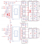
R=4x10 ohm, C=4x330 pF
Capacitors are connected to PCB ground plane after scratching the paint in two points.
By the way, a piece of 2.54mm strip contact can be used as input connector (can be seen in first picture)
Hello, how did you calculated the RC Network? I can’t find those 330pF capacitors so I would need an alternative to those.
Thanks in advance.
- Home
- Amplifiers
- Class D
- TPA3116D2 Amp