I can tell what they are:
Elite 2.2uF 50V NP
if there would not be 5 of them they could also be the signal input caps.
i have no idea.
saturnus is right most of the times, while i'm a noob.
i think 'local decoupling' is about the dc input.
It's not FCC qualified either. The FCC logo is a Chinese lookalike.
***
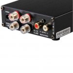
The box the unit is sent in and the unit itself both include the FCC certification logo and the CE logo (as in Conformité Européenne). This is the manufacturer's certification that the unit complies with the standards of the FCC and CE.
Now we all know that some Chinese products (as well as products from many other places) contain statements on them that may not be correct.
However, my own use and informal testing of the unit would support that it does not have noise emission problems in my setting. But I'm just an end user, not the manufacturer.
See photo of rear panel attached.
Attachments
Last edited:
If the input signal has already passed the input capacitors it's not that subjective to noise being differential. Also remember that the GVDD pin annoyingly placed in the center of the chip also has to be decoupling by at least 1µF. 2.2µF could also be used if it means you can buy bulk and thereby save money.
the more i get into this whole thing and study recommended implementations from various datasheets, the more i wonder why the pinouts of the chips are how they are.
my guess is that they could do much better pin layout if they had possible board layouts in mind much earlier in the design process.
what i learn especially out of this thread is how important a tight board layout is.
The pin outs on this chip are actually pretty well thought out compared to many other chips. All input and output pins are on different sides. The power and ground connections as close as possible to where they are actually used. The GVDD pin also should be in the middle as it's the gate voltage driver. What could have been improved was to have all the control inputs on one end and the signal input on the other. I also have no clue why they didn't put the AVDD on the input side to make it easier to separate the PVDD from AVDD. For that purpose they could have placed an extra GND in the middle on the output side to make it symmetrical.
One thing that really annoys me though is why the AM2 pin is there at all. It can only be used to set the switching frequency to 1khz but that is not supported, and not recommended for any design at all. That pin could have been used for AVDD instead (with the reconfiguration above in mind).
Last edited:
***
The box the unit is sent in and the unit itself both include the FCC certification logo and the CE logo (as in Conformité Européenne). This is the manufacturer's certification that the unit complies with the standards of the FCC and CE.
That's not a proper CE marking - this one is for "China Export", and means practically nothing, since it isn't controlled by anybody.
The proper "CE" (as in Conformité Européenne) marking looks differently - I suggest you check this issue online, e.g.:
https://www.google.com/search?q=CE+...5HML8ywP7_IDQCA&ved=0CEwQsAQ&biw=1418&bih=908
Wikipedia "CE marking" article:
CE marking - Wikipedia, the free encyclopedia
Regardless of the "fake" CE mark, if the unit doesn't have any serious emission problems, I'd leave it at that. Works well, sound is OK, so this isn't an issue - unless you want to resell it on the EU (or USA) market: that would be quite an issue then, and would require (expensive) re-certification for the local EU/USA market.
I can tell what they are:
Elite 2.2uF 50V NP
They are input coupling caps, bypassed by red "wima" small value film. 5th probably gvdd, not recommended size TI datasheet then, Ydbz has larger value gvdd aswell.
The pin outs on this chip are actually pretty well thought out compared to many other chips. All input and output pins are on different sides. The power and ground connections as close as possible to where they are actually used. The GVDD pin also should be in the middle as it's the gate voltage driver. What could have been improved was to have all the control inputs on one end and the signal input on the other. I also have no clue why they didn't put the AVDD on the input side to make it easier to separate the PVDD from AVDD. For that purpose they could have placed an extra GND in the middle on the output side to make it symmetrical.
One thing that really annoys me though is why the AM2 pin is there at all. It can only be used to set the switching frequency to 1khz but that is not supported, and not recommended for any design at all. That pin could have been used for AVDD instead (with the reconfiguration above in mind).
Support forum TI has questions and answers, I believe I read about designers very pleased with 1.2Mhz switching freq. and quality they get from using that. TI also states that THD could be decreased using higher switching frequency, but I guess layout is hard enough with 400khz 🙂 If TI standard config for EVM would be 1.2mhz not 1 chinese would make effort to lower it to 400khz, now not 1 chinese we know raises it 🙂
Support forum TI has questions and answers, I believe I read about designers very pleased with 1.2Mhz switching freq. and quality they get from using that. TI also states that THD could be decreased using higher switching frequency, but I guess layout is hard enough with 400khz 🙂 If TI standard config for EVM would be 1.2mhz not 1 chinese would make effort to lower it to 400khz, now not 1 chinese we know raises it 🙂
Sorry. You're right the AM2 sets the switching frequency to 1.2Mhz. AM1 and AM0 both HIGH is 1mhz. Both are smack in the middle of radio bands though so that's not advisable. Certainly not for DIY designer. 500khz is probably the best frequency setting as it doesn't interfere with any radio bands and it doesn't require much more consideration of use than 400khz. It's also means output filters will perform better so improved sound quality is probable.
At 1mhz or 1.2mhz switching frequency the ternary (1SPW) modulation mode should probably be used to reduce switching losses.
Last edited:
Maybe, don't know if THD drops would that indicate that switching losses aren't really an issue? I do know Hypex mentioned somewhere ~600khz at this time is most ideal switching frequency, higher has some disadvantages they claimed, could be they just couldn't find producer that could make chips without those disadvantages for a price they liked 🙂 ?? 1.2mhz harmonics might be in crowded airspace, filterless with wires to tall speakers could be fun then 😀
I am designing an amplifier using TPA3116 the right time, and so far not had good results.
regarding the layout initially used a topology convert TPA SMD to PTH, and use all the wrapping other components in PTH. (did not work, I dunno why ??)
Now using it all in SMD, it worked.
The layout can influence the operation of the circuit ????
Or quality (tolerance) components ???
I look back, attached photos.
That's not a proper CE marking - this one is for "China Export", and means practically nothing, since it isn't controlled by anybody.
The proper "CE" (as in Conformité Européenne) marking looks differently - I suggest you check this issue online, e.g.:
https://www.google.com/search?q=CE+...5HML8ywP7_IDQCA&ved=0CEwQsAQ&biw=1418&bih=908
Wikipedia "CE marking" article:
CE marking - Wikipedia, the free encyclopedia
Regardless of the "fake" CE mark, if the unit doesn't have any serious emission problems, I'd leave it at that. Works well, sound is OK, so this isn't an issue - unless you want to resell it on the EU (or USA) market: that would be quite an issue then, and would require (expensive) re-certification for the local EU/USA market.
***
It appears the unit is already being sold and shipped to Europe by the authorized distributor, Shenzhen Audio.
I've emailed them to ask if the unit conforms to the CE standards - as in Conformité Européenne. I'll report back their reply.
Last edited:
Some European high end brands use the fake CE marking too, check six moons LOL they probably have enclosures made in China 🙂 Audiopower.it has fake CE on pcb boards produced in Italy, or had, Bang&Olufsen Icepower, made in China btw, has fake CE on pcb sometimes etc etc
Even when careless producers could use real CE marking they make mistakes. Chinese producers use fake parts everywhere, fake markings too, ChinaExport logo was intended to confuse and is very succesfull.
Even when careless producers could use real CE marking they make mistakes. Chinese producers use fake parts everywhere, fake markings too, ChinaExport logo was intended to confuse and is very succesfull.
I've emailed them to ask if the unit conforms to the CE standards - as in Conformité Européenne. I'll report back their reply.
If it's FCC qualified it has a traceable FCC ID# as well.
Logo is fake or careless, probably just fake hereIf it's FCC qualified it has a traceable FCC ID# as well.
https://apps.fcc.gov/kdb/GetAttachm...belling Quick Guide V01&tracking_number=27980
About modding my second danzz-board:
DC caps are chemicon psg 390 uf on my board.
I have a few high quality electros: 2700uf with r.c. 4.1A and 4700uf with r.c. 4.96A.
Power sources are either a 24V 6.5A smps (sure-electronics) or ~20V from sla batteries.
Question:
Where should which caps go?
Only into the enclosure of the amp?
Some into the enclosures of the power supplies?
Do the batteries really need that?
How much capactiy would be too much, how much is good?
ceramic caps are often recommended for an upgrade of the bootstrap caps.
is there any downside in using polyester caps for this application?
the lc filter i have already upgraded with matching values, but cheap components.
caps are polyester, too.
would those inductors fit the danzz-board:
http://www.conrad.de/ce/de/product/...2-H-Wuerth-Elektronik-744311022-1-St?ref=list
?
About the EMI snubber:
Polyester or ceramic or a mix of both?
***
I just purchased the SMSL SA-60 amp.
What do you think about the Headphone output of this SMSL SA-60 ? 😕
I'm searching specifications about its headphone amp. 🙂
What do you think about the Headphone output of this SMSL SA-60 ? 😕
I'm searching specifications about its headphone amp. 🙂
It does not have a headphone output. The jack plug on the front is a mini-jack input . It even clearly says so on the amp.
i would have tried to place the caps you use for signal input to place right above the other pin, which is closer to the chip.
What would the reason be?
The capacitor leads carry audio signals only.
The sole purpose of the input capacitors is to block DC voltages. It does not matter where in the inptr circuit you put the capacitors, you can even put it at the source end of the connection to the amplifier.
What would the reason be?
The capacitor leads carry audio signals only.
The sole purpose of the input capacitors is to block DC voltages. It does not matter where in the inptr circuit you put the capacitors, you can even put it at the source end of the connection to the amplifier.
ok.
i thought i read something like this in the datasheet.
i must mistake this with the dc-caps, right?
does anyone have answers to my questions about polyester-caps and position of bigger electros?
What do you think about the Headphone output of this SMSL SA-60 ? 😕
I'm searching specifications about its headphone amp. 🙂
***
SMSL confusingly calls it a "3.5mm headphone jack input." It's a "headphone-type jack," (in that it's 3.5mm as headphone jacks commonly are on small devices) but not a headphone output jack. It's an input jack, for easily picking up a signal from a small player device like an MP3 player.
I haven't tried the 3.5mm "headphone" input yet, am using the RCA input jacks on the back.
I don't believe the 3116 topology can support a headphone output, because the two output channels should never shorted out to each other (in fact the SA-60 carries a warning not to short the outputs). Many headphones use a common ground for both left and right transducers, which would short together the two output channels. So the 3116 is for speakers only. Also, the output is awfully hot for headphones.
Good headphone amps that I own and like are the Bottlehead Crack (if you want OTL tube design in kit form), and the new FiiO Kilimanjaro2 E11K (if you want portable solid state).
Les
Last edited:
- Home
- Amplifiers
- Class D
- TPA3116D2 Amp