Sure. Epoxy will do the trick. If you dont have a digital solder station you should consider this to have more control over the solder temperature. Ofcourse soldering too long will make this pretty much unavoidable.
This weekend I attempted to remove the stock inductors for the YJ blue/black board. I was generally successful, except that I pulled up on of the solder pads. It's still connected to the trace, but the "open" end peels up a bit.
Can I just use a tiny bit of high-temperature epoxy to glue it back down to the PCB? Anyone have any suggestions?
Also, in my haste, I hit one of those 0.68uF output filter caps with my soldering iron, and melted the corner a bit... how rugged are these film caps? Is the cap likely a goner, or is it still viable?
Today I took one of the other modded blue/black boards removed the stock inductors
and replaced with the recommended Bourns...In comparison to the coilcraft the Bourns wins hands down.. stronger bass and the hard edge in voices are mostly gone.I was skeptical before doing any mods that it could be made to sound better. I'll say also the inductors so far have had the greatest effect.
and replaced with the recommended Bourns...In comparison to the coilcraft the Bourns wins hands down.. stronger bass and the hard edge in voices are mostly gone.I was skeptical before doing any mods that it could be made to sound better. I'll say also the inductors so far have had the greatest effect.
Today I took one of the other modded blue/black boards removed the stock inductors
and replaced with the recommended Bourns...In comparison to the coilcraft the Bourns wins hands down.. stronger bass and the hard edge in voices are mostly gone.I was skeptical before doing any mods that it could be made to sound better. I'll say also the inductors so far have had the greatest effect.
Can you please post photos of your mods to show us how you oriented the Coilcraft and the Bourns inductors?
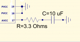
Significant improvements from separating out pin17 (analog +ve supply) from its two near neighbours which are the output stage supply. My first tweak is 3.3ohms in series and 10uF 1206 to the plane. This has brought the soundstage alive and almost killed the sibilance on voice, very worthwhile mod.
Thanks for your input.
That will sure change the noise floor & sound of the YJ boards.
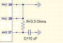
Just to get things clear, PIN 17 to resistor in series and then cap to ground like in the attached schematic ?
Attachments
TI E2E
Question: Is it possible to run a lower voltage on AVCC than PVCC? (tpa3118)
Posted by Paul C. Chen on Apr 08 2014 09:31 AM Suggested Answer
Mastermind30550 points
Hi Gmarsh,
AVCC and PVCC need to be at the same voltage level.
reg,
Paul.
I read discription like this voltagedivider.

Question: Is it possible to run a lower voltage on AVCC than PVCC? (tpa3118)
Posted by Paul C. Chen on Apr 08 2014 09:31 AM Suggested Answer
Mastermind30550 points
Hi Gmarsh,
AVCC and PVCC need to be at the same voltage level.
reg,
Paul.
I read discription like this voltagedivider.
Just to get things clear, PIN 17 to resistor in series and then cap to ground like in the attached schematic ?
Cap to ground is from pin17, resistor (currently 3.3ohms, subject to further listening) is between pin18 and pin17. Thus its filtering the output stage supply to remove HF put there by the output switching transitions.
@irribeo - yes where 'Vin' is PVCC and 'Vout' is AVCC.
Last edited:
Cap to ground is from pin17, resistor (currently 3.3ohms, subject to further listening) is between pin18 and pin17. Thus its filtering the output stage supply to remove HF put there by the output switching transitions.
Thanks, I think I got it.
abraxalito and irribeo
Have you guys tried any good tk2050 implementation ?
How do you think these compare to the tpa3116 ?
Attachments

Last edited:
I switched to PBTL because in BTL the ch with PVCC connected to AVCC always seemed to have little more noise. More people here commented on noise difference in ch's. Is it related to AVCC connection, or is it something else?
Have you guys tried any good tk2050 implementation ?
No the TPA3116 is my first foray into switching amps from a DIY point of view. I had a Tripath amp inside my PC going back over 12 years now and I liked the sound.
Incidentally the connection to pin 18/19 isn't to earth as your schematic shows, its to the positive supply.
It might be - do you have a part/value to suggest? It would probably need a resistor in addition in parallel, for damping.
No the TPA3116 is my first foray into switching amps from a DIY point of view. I had a Tripath amp inside my PC going back over 12 years now and I liked the sound.
Incidentally the connection to pin 18/19 isn't to earth as your schematic shows, its to the positive supply.
I am asking because I am still not sold to the tpa3116. Bellow 3 kHz my tripath outperforms the current builds i have of the tpa3116.
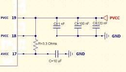
Dang, I swear I was doing it wrong for the third time now. Could not find the appropriate symbol, got distracted and voila. GND
I switched to PBTL because in BTL the ch with PVCC connected to AVCC always seemed to have little more noise. More people here commented on noise difference in ch's. Is it related to AVCC connection, or is it something else?
Interesting.
I have four different boards designs and all have different behavior on what concerns noise and output mode:
YJ black/blue with line filter caps: more noise from the right channel, less noise in PBTL.
tpa3118 with on/off built in volume: noise in BTL, more noise in PBTL
yj red board: noise in in BTL, less noise in PBTL
Audiobah green board: pretty much noiseless, no matter if BTL or PBTL
I will have a try the mod that abraxalitos suggested and see how the overall noise changes.
For the blue/black YJ board used some line filter type x2, 1.2uF ( 😱 ) caps and also mixed config line x2 1.2 uF for INPR and for the other channel standard 1uF on INPL . Not amazed by this board sq.
Attachments
Last edited:
Have you guys tried any good tk2050 implementation?
About two years ago (IIRC), I built a little amp with the HiFiMeDIY T2 (tk2050-based) board and a Connex 300-watt SMPS.
Then I tried the $10 Sure TPA3110 board. No mods, didn't even put it in a case (direct-connect all connections to the board), basic 12v/2a wall-wart, and I remember immediately noticing an improvement.
That was about a year ago, so I don't recall the details of exactly how it sounded better, but I do recall it was immediately obvious.
So I stuck with the 3110, until the 3116 interest got going recently. I tweaked my 3110 just a bit (bigger onboard DC caps, big cap across the DC input), and added a volume control.
On my 3116, I used the YJ blue/black board and kept it stock (other than adding a volume pot), and I'd say it's quite close to my modded 3110, but I think the 3110 still has the edge.
I haven't compared the 3116 to the TK2050, but, I will say that the move from tk2050 to tpa3110 was immediately noticeable, while the differences between the 3110 and 3116 are minimal.
Note that I suspect there is some limit to the amount of resolution I can perceive with my current speakers. Also, I'm definitely still developing my critical listening skills. So take all this with a big grain of salt. Definitely not the last word here, just the experience of one random guy on the Internet. 🙂

Just receive a black board but doesn't look like to be much room for removing the inductors.
I had to remove all the surrounding components: the four 0.68uF caps, the power terminal block, and the DC power caps.
I suspect someone with a small enough soldering iron and the hands of a surgeon could probably remove them without removing the surrounding parts... but that ain't me!
Can anybody confirm if this aliexpress amp is the same as the yuan jing?
TPA3116 Amplifier Assembled Board 50W + 50W Official Version Amp Board-in Consumer Electronics on Aliexpress.com
TPA3116 Amplifier Assembled Board 50W + 50W Official Version Amp Board-in Consumer Electronics on Aliexpress.com
Can anybody confirm if this aliexpress amp is the same as the yuan jing?
yes its the same. At least from the one i got from Aliexpress, has the same specs and look from the yuan jing one.
Im thinking of putting a potentiometer on it, but cant figure out how many K it should be ?
Also i did not get any diagram for it
Anybody knows about this tpa3116 amp if its good?
Digital power amplifier HiFi fever TPA3116+LM1036N 50W+50W preamp tone amp - iBuyLa_Tmall_Taobao Angent - Online Shopping at iBuyLa.com in Singapore
Digital power amplifier HiFi fever TPA3116+LM1036N 50W+50W preamp tone amp - iBuyLa_Tmall_Taobao Angent - Online Shopping at iBuyLa.com in Singapore
Yeee I looked at audiobah board again. If close decoupling of tpachip is important, I always wonder how audiobah board can be good. I think it is board with largest distance between tpachip and power decoupling ceramics.
(and power trace crossing under inputsignaltraces...also weird)
(and power trace crossing under inputsignaltraces...also weird)
Last edited:
- Home
- Amplifiers
- Class D
- TPA3116D2 Amp