I just got two blue boards (43rmb from Taobao) delivered.
First thing I did was remove the stock (22uH) inductors and measure them. DCR is respectable, around 40mohms but at 100kHz (the high frequency limit of my LCR meter) this has gone up to 0.48ohms. Unacceptably high in my book especially as it'll be higher still at the switching freq. So I'll experiment with alternative output inductors.
Second point is there's a single ground fill used for the 0V connections, this I'll hack into to get some semblance of star earthing for the audio feed. Its rather fiddly as isolating the input ground means desoldering the input connector to break the thermal reliefs on the top side. Ground fills like this are a problem for audio quality because the ground currents get all mixed up and with a switcher there are some fairly heavy currents flowing - we don't want any impedances shared between power and signal grounds.
Pardon me for asking these naive questions - I assume DCR = DC resistance, why would it changes with frequency? The inductive reactance of course will increase as frequency increase, right? I thought that was the whole idea of using a LC output filter to drain all the unwanted high frequency to ground.
Regards,
The resistance changes with frequency because the current does not occupy the whole conductor as the frequency goes up. Also the ferrite material isn't linear, has some loss as it traverses its B-H curve. Higher frequency means more loops per second, meaning more loss.
Yes the inductive reactance increases with frequency or it'd not be an inductor. Yes we want the unwanted freqs eliminated from the output, but preferably recycled back to the power supply rather than dissipated as heat. The latter is the case when the output inductors have high losses.
Yes the inductive reactance increases with frequency or it'd not be an inductor. Yes we want the unwanted freqs eliminated from the output, but preferably recycled back to the power supply rather than dissipated as heat. The latter is the case when the output inductors have high losses.
Good news, I got the Taobao TPA3116 2.0 installed into an hdd enclosure plate that I had lying around for the time being using rubber feet as the standoffs and hot glue gun for mounting.
I didn't even use my HP 19v 7.1A power supply yet, I only used a 15v 2.7A unit and boy oh boy am I impressed right off that bat. Very little tiny pop of the speakers when turning the unit on, compared to a big pop that I had running my NuForce Icon 1 amp. I don't even have to crank even 1/4 volume and its so loud!!!
Going to let it burn in but listening to Jack Johnson's Go On already sound fantastic, and seems like this has a great low end to it. Instant clarity right off the bat. I'm already loving it and I haven't even got 10 minutes of usage out of it. I'll update again later on once I listen to it more often.
Good news, I got the Taobao TPA3116 2.0 installed into an hdd enclosure plate that I had lying around for the time being using rubber feet as the standoffs and hot glue gun for mounting.
I didn't even use my HP 19v 7.1A power supply yet, I only used a 15v 2.7A unit and boy oh boy am I impressed right off that bat. Very little tiny pop of the speakers when turning the unit on, compared to a big pop that I had running my NuForce Icon 1 amp. I don't even have to crank even 1/4 volume and its so loud!!!
Going to let it burn in but listening to Jack Johnson's Go On already sound fantastic, and seems like this has a great low end to it. Instant clarity right off the bat. I'm already loving it and I haven't even got 10 minutes of usage out of it. I'll update again later on once I listen to it more often.
Alright, looks like we have another winner!! Thank you for the update.
Regards,
I just got two blue boards (43rmb from Taobao) delivered.
First thing I did was remove the stock (22uH) inductors and measure them. DCR is respectable, around 40mohms but at 100kHz (the high frequency limit of my LCR meter) this has gone up to 0.48ohms. Unacceptably high in my book especially as it'll be higher still at the switching freq. So I'll experiment with alternative output inductors.
Second point is there's a single ground fill used for the 0V connections, this I'll hack into to get some semblance of star earthing for the audio feed. Its rather fiddly as isolating the input ground means desoldering the input connector to break the thermal reliefs on the top side. Ground fills like this are a problem for audio quality because the ground currents get all mixed up and with a switcher there are some fairly heavy currents flowing - we don't want any impedances shared between power and signal grounds.
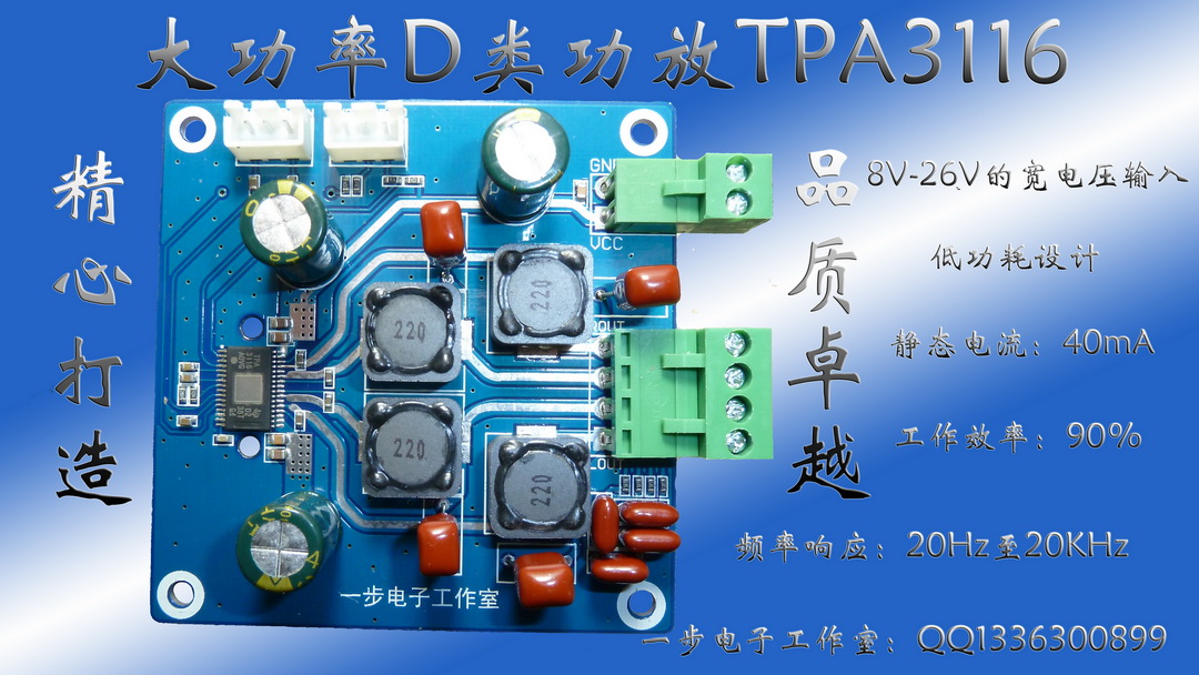
This blueboard you mean?
An externally hosted image should be here but it was not working when we last tested it.
Yep, that be the one 🙂 The audio input connector is at top left but its gnd pin goes directly to the plane. If you read the DS you'll see they recommend that for SE (single ended) inputs the -ve input pin should go to the gnd wire of the source as closely as possible. Whilst I haven't examined the layout in detail yet it does look as though this recommendation's been ignored, instead the groundfill local to the IC has been used as the -ve input reference.

Attachments
Hello
I would ask, on this board TPA3116 Class-D 2.0 Stereo Power Amplifier Board [50W+50W] With Audio Cable | eBay
can I replace the 1 uf blue caps with 2,2 uf mundorf polypropilene caps ?
thank you
I would ask, on this board TPA3116 Class-D 2.0 Stereo Power Amplifier Board [50W+50W] With Audio Cable | eBay
can I replace the 1 uf blue caps with 2,2 uf mundorf polypropilene caps ?
thank you
I didn't have those at my disposal and I couldnt wait any longer 😀😀
Plus with hot glue gun, I can always peel it away if I ever need to remove anything. So its just as versatile. 😛
Audio input grounding mods
As I suspected, on closer examination of the inputs to the TPA3116, the ground fill locally to the chip has been used as the -ve audio reference point, meaning noise is coupled in by virtue of the fill doing more than one grounding function. Rather than hack the PCB I shall lift the two caps' 0V connections (arrowed) and give them a dedicated ground back to the connector ground pin.
As I suspected, on closer examination of the inputs to the TPA3116, the ground fill locally to the chip has been used as the -ve audio reference point, meaning noise is coupled in by virtue of the fill doing more than one grounding function. Rather than hack the PCB I shall lift the two caps' 0V connections (arrowed) and give them a dedicated ground back to the connector ground pin.
Attachments

Hello
I would ask, on this board TPA3116 Class-D 2.0 Stereo Power Amplifier Board [50W+50W] With Audio Cable | eBay
can I replace the 1 uf blue caps with 2,2 uf mundorf polypropilene caps ?
thank you
That's the mode that someone had tried and reported favourable results. If I remember correctly, the datasheet suggest input cap of 3.3 uF to go with 26 db gain.
Regards,
Yep, that be the one 🙂 The audio input connector is at top left but its gnd pin goes directly to the plane. If you read the DS you'll see they recommend that for SE (single ended) inputs the -ve input pin should go to the gnd wire of the source as closely as possible. Whilst I haven't examined the layout in detail yet it does look as though this recommendation's been ignored, instead the groundfill local to the IC has been used as the -ve input reference.
When you say the negative input is connected to "ground fill" is that the same as the ground plane on the board? Isn't the ground plane so big that it essentially has very low impedance that it acts like a star hub topology? From the standpoint of minimizing noise due to ground loops isn't that the best way to have minimal noise? I think adding a separate unshielded wire from the cap to the negative of the input may actually make it more susceptible to noise pickup as you have a wire raised up off the ground plane and acting more like an antenna for the 400khz RF. ?
The ground plane isn't a substitute for a star earth - it does have significant impedance. With a class D amp there are significant currents (amps) flowing in the output stage and for decent audio we do need not to have those currents flowing in shared grounds for the inputs. Yes a wire is susceptible to noise pick up, but at 400kHz a wire does need to be rather long to act as an antenna.
Ultimately ears are the arbiter and if this modification sounds bad then I'll modify it.
Ultimately ears are the arbiter and if this modification sounds bad then I'll modify it.
That's the mode that someone had tried and reported favourable results. If I remember correctly, the datasheet suggest input cap of 3.3 uF to go with 26 db gain.
Regards,
Thank you very much !!
As I suspected, on closer examination of the inputs to the TPA3116, the ground fill locally to the chip has been used as the -ve audio reference point, meaning noise is coupled in by virtue of the fill doing more than one grounding function. Rather than hack the PCB I shall lift the two caps' 0V connections (arrowed) and give them a dedicated ground back to the connector ground pin.
Crud, so not a total wiener!

The ground plane isn't a substitute for a star earth - it does have significant impedance. With a class D amp there are significant currents (amps) flowing in the output stage and for decent audio we do need not to have those currents flowing in shared grounds for the inputs. Yes a wire is susceptible to noise pick up, but at 400kHz a wire does need to be rather long to act as an antenna.
Ultimately ears are the arbiter and if this modification sounds bad then I'll modify it.
I don't have any hissnoise with ear in speaker, but do hear soft low freq hum with ear in speaker without music playing🙂 Could be mains related? My cinch shield is connected to a mks cap and groundplane same place and from that cap to negative input. Cinch signal from simular mks cap to possitive input. I have boards unconnected now because I wanted to put on heatsinks (3116 toppad untill now unconnected from groundplane). If I disconnect mkscap for shield from 3116 groundplane do I need to put shield through ferrite bead, or should I not disconnect?
Sorry, I can't visualize what you're asking here.
I wound some pot core inductors ( 9 turns home-made rope wire for low skin/proximity losses, AL=250 core) and bodged them in - a little larger than the stock inductors. I have around 400,000uF decoupling it - the board sits atop a hexacap. Initial listening indicates bass is rather indistinct, dynamics are nowhere special and there's some sibilance on voice, hardness on brass and soundstage depth is lacking. Not at all bad for the money or the efficiency though - very impressed with how little current its drawing. My home-made inductors due to their lower loss have reduced the quiescent current by 10-15mA. I'll look into regrounding and see if there are any SQ improvements to be had, particularly on sibilance.
I wound some pot core inductors ( 9 turns home-made rope wire for low skin/proximity losses, AL=250 core) and bodged them in - a little larger than the stock inductors. I have around 400,000uF decoupling it - the board sits atop a hexacap. Initial listening indicates bass is rather indistinct, dynamics are nowhere special and there's some sibilance on voice, hardness on brass and soundstage depth is lacking. Not at all bad for the money or the efficiency though - very impressed with how little current its drawing. My home-made inductors due to their lower loss have reduced the quiescent current by 10-15mA. I'll look into regrounding and see if there are any SQ improvements to be had, particularly on sibilance.
Significant improvements from separating out pin17 (analog +ve supply) from its two near neighbours which are the output stage supply. My first tweak is 3.3ohms in series and 10uF 1206 to the plane. This has brought the soundstage alive and almost killed the sibilance on voice, very worthwhile mod. I rather suspect that HF ripple from the output stage easily floods the analog stage LDO reg (see DS p4 for internal diagram) so this passive filter's giving the signal processing stages a cleaner supply. I'm also bypassing the power connector to the board and feeding the ground in directly to the hexacap, meaning the switching currents aren't flowing across the groundfill now. Next up - move the grounding of the output filter caps off the fill....
<edit> Now have 470uF in parallel with the original 10uF ceramic, more delicacy of sound. Clearly this supply rail is a promising vein to mine....😛
<edit> Now have 470uF in parallel with the original 10uF ceramic, more delicacy of sound. Clearly this supply rail is a promising vein to mine....😛
Last edited:
This weekend I attempted to remove the stock inductors for the YJ blue/black board. I was generally successful, except that I pulled up on of the solder pads. It's still connected to the trace, but the "open" end peels up a bit.
Can I just use a tiny bit of high-temperature epoxy to glue it back down to the PCB? Anyone have any suggestions?
Also, in my haste, I hit one of those 0.68uF output filter caps with my soldering iron, and melted the corner a bit... how rugged are these film caps? Is the cap likely a goner, or is it still viable?
- Home
- Amplifiers
- Class D
- TPA3116D2 Amp