Tauro,
two diodes, back to back, will stop current flowing in both directions.
There is no way that back to back diodes had a hum reducing effect and allowed the transformer to work..
You did something else !
two diodes, back to back, will stop current flowing in both directions.
There is no way that back to back diodes had a hum reducing effect and allowed the transformer to work..
You did something else !
Hi,
I never used the bridge but I looked it in how it is done . I was thinking that when you used the bridge you have two diode in series in one direction and the other two in reverse direction. I think it is was my fault not to look it and give a wrong suggestion. I apologized fro the wrong advice. Anyway attached it is a drawing showing how I did it in my 3 LM3386 amplifiers.
I never used the bridge but I looked it in how it is done . I was thinking that when you used the bridge you have two diode in series in one direction and the other two in reverse direction. I think it is was my fault not to look it and give a wrong suggestion. I apologized fro the wrong advice. Anyway attached it is a drawing showing how I did it in my 3 LM3386 amplifiers.
Attachments
those two diodes are in parallel. They are not in series, they are not back to back.
Parallel but in opposite direction ( I use the term inverse parallel) to allow current to pass in both directions.
I consider your grounding diagram to be a very bad layout and should not be copied by anyone.
Parallel but in opposite direction ( I use the term inverse parallel) to allow current to pass in both directions.
I consider your grounding diagram to be a very bad layout and should not be copied by anyone.
Happy Holidays, Guys;
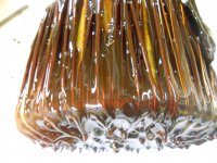
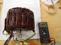
Just another minor update. The Toroid from the Crest CA-18 will be receiving it's 20th and final dip in a couple of days. Although there is some controversy here as to how far the varnish has penetrated, tapping on the transformer is producing a noticeably more 'solid' sound after the most recent dips. After dip no. 20, I absolutely promise to put the AC to it. I am psyching myself (up or down) for the results. Here is what it looks like after dip 19. If it's not solid, at least it's got to be air tight!
Just another minor update. The Toroid from the Crest CA-18 will be receiving it's 20th and final dip in a couple of days. Although there is some controversy here as to how far the varnish has penetrated, tapping on the transformer is producing a noticeably more 'solid' sound after the most recent dips. After dip no. 20, I absolutely promise to put the AC to it. I am psyching myself (up or down) for the results. Here is what it looks like after dip 19. If it's not solid, at least it's got to be air tight!
Attachments
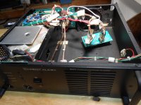
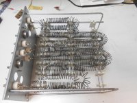
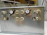
My other project, the Crest 8001 has been disassembled and cleaned. It is ready for the 'treadmill', I think. There was much controversy regarding cleaning procedures, so I took a minimalist approach; tooth brush and paint brush with vacuuming. I finally used compressed air but avoided the (bias) and volume pots out concern regarding blowing dirt INTO non accessible areas.
Attachments
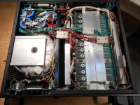
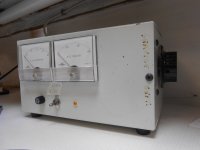
One more 'after' picture. Also attached is my variac test box. The AC Ammeter is 1 Amp FSD, but variac has a 4.5 Amp rating. Something I've been meaning to do for years, and now has become a necessity with these monster Crest Amps is; install a shunt across the Ammeter to increase the capacity. After some experimenting, the shunt turned out to be about 14 inches of 18 gauge wire to increase FSD to about 3 Amps. The switch on front panel is for the 'shunt'
Attachments
OK yes I'm stalling, but here is my 'bullet proof' home made dummy load. This was a furnace element. There are 4 sections, I shortened each element to 8 ohms. I then arranged series-parallel jumpers to again yield 8 ohms. The resistance cold was approx 7.9 to 8 ohms. I connected my variac directly to the dummy load and found resistance maintained exactly, at least up to 24 Volts, 3 Amps.
Happy New Year, Everyone!
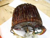
Well, I have 'dipped the toroid', FOR THE LAST TIME!
I put the power to it;......drum roll please, DEAD QUIET. In fact, I had to put my meter on the secondaries to see that it was actually on!
20 dips, and $100 more on my Hydro bill, running the heater to dry it between dunks. Definitely not a practical solution, but it is PERFECTLY quiet, so IMHO, it was worth it. I just have to carefully remove the 'dribbles' and fit the ferrous shield. I have some vinyl sheet for that; will post photos asap
Attachments
Happy New Year, Everyone!
Well, I have 'dipped the toroid', FOR THE LAST TIME!
I put the power to it;......drum roll please, DEAD QUIET. In fact, I had to put my meter on the secondaries to see that it was actually on!...
Compliments! Excellent news to start the New Year, or a nice seasonal present if you are a Xmas believer.
I may try this myself, but with epoxy so I only have to do one soak.😉
Best wishes
David
Hi Folks
Just want to thank you all again for your help with my Crest CA-18. The amp has a 5 watt resistor in series with the DC fans. The amps is now civilized enough for my home theatre, and is literally blowing people away with the jaw dropping bottom end.
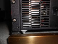
I have turned the nylon rack feet up side down, to support the amp and help to get it in and out (hopefully not soon) of the rack.
I am now attacking my system from the front end, and would greatly appreciate advice from all of you who have been so generous with your time so far.
I have started a new thread called "Dumb Questions about Digital Music sources".
Thanks again, Peter S
The Crest CA-18 makes even my old Phase Linear 700 look pretty, but it's not about cosmetics, right!
Just want to thank you all again for your help with my Crest CA-18. The amp has a 5 watt resistor in series with the DC fans. The amps is now civilized enough for my home theatre, and is literally blowing people away with the jaw dropping bottom end.
I have turned the nylon rack feet up side down, to support the amp and help to get it in and out (hopefully not soon) of the rack.
I am now attacking my system from the front end, and would greatly appreciate advice from all of you who have been so generous with your time so far.
I have started a new thread called "Dumb Questions about Digital Music sources".
Thanks again, Peter S
The Crest CA-18 makes even my old Phase Linear 700 look pretty, but it's not about cosmetics, right!
Attachments
Hi again folks!
Just dusting off this thread, hoping that I might find more advice from some of you who been so helpful with my Crest amp in the past.
The Toroid noise is honestly a non issue now. I believe that the last 7 months of occasional use may have further cured some of the varnish in the deeper layers.
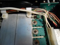
The fan noise issue remains...Again, contrary to the educated advice I have received, I inserted one resistor in the negative side of the fan control power. The value was found by trial and error, passing just enough current to keep the fans from stalling. The problem arises after an hour or so. Unsurprisingly, things warm up a bit, and the fans speed up to the point where the noise is objectionable during silent passages.
I have been unable to locate quieter fans of this size (119 mm sq., for 3-rack space cabinets, 24 volt, 5 watt) The fans are Papst, made in Germany and claim to be fairly quiet, 45db(A).
I am determined to create the ultimate monster home stereo system, and still feel that this Crest CA-18 could be a great amp for my RCF 18" woofers (140 Hz and down).
I understand that heat is a concern for any amp, especially this amp with such a tightly packed component layout, I continue to hunt for a modification that could be adopted, given the extremely light load conditions of this amp.
Thanks again, Peter in Canada
Just dusting off this thread, hoping that I might find more advice from some of you who been so helpful with my Crest amp in the past.
The Toroid noise is honestly a non issue now. I believe that the last 7 months of occasional use may have further cured some of the varnish in the deeper layers.
The fan noise issue remains...Again, contrary to the educated advice I have received, I inserted one resistor in the negative side of the fan control power. The value was found by trial and error, passing just enough current to keep the fans from stalling. The problem arises after an hour or so. Unsurprisingly, things warm up a bit, and the fans speed up to the point where the noise is objectionable during silent passages.
I have been unable to locate quieter fans of this size (119 mm sq., for 3-rack space cabinets, 24 volt, 5 watt) The fans are Papst, made in Germany and claim to be fairly quiet, 45db(A).
I am determined to create the ultimate monster home stereo system, and still feel that this Crest CA-18 could be a great amp for my RCF 18" woofers (140 Hz and down).
I understand that heat is a concern for any amp, especially this amp with such a tightly packed component layout, I continue to hunt for a modification that could be adopted, given the extremely light load conditions of this amp.
Thanks again, Peter in Canada
It would be fairly simple to design a variable speed fan system with a tiny microcontroller and a temperature sensor on the heat sink. That way you could run the fan as slow as it is safe to according to the operating conditions of the amp. PWM is a better way to drive the fan too.
Hi jwilhelm;
Nice to hear from you again! As you may have concluded, I am trying to finesse this fan problem, buy my skill set tool box is mostly full of rusty sledge hammers. I don't have an abilty to design a pulse width modulation (I assume that is what you where referring to) or print a PCB. I was hoping for a clever solution requiring a minimum of components, to avoid having to produce a PCB.
I have an idea, perhaps you could help me with the feasibility. I found that the fan noise was tolerable at approx 6 volts, but of course, the voltage slowly creeps up. (There are already temp sensors on the 2 heat sink modules). I envision (an external) fixed power supply feeding the fans. When heat sink temp rises, and the fan speed controller in the amp increases its voltage, I would like to come up with a very simple circuit (relay or zener?) that would ignore the increase until it reaches a threshold (to be determined) at which point, it switches to the higher (internal) fan supply for temporary cooling.
I believe that the fan speed is a servo of some type, but my application would be better suited by allowing a 'step' in the temperature rise. The cooling was designed to accommodate the 5000 watt (bridge mode into 4 ohms) output. I imagine there would be considerable heat sink temperature, at this output, even at ful fan cooling. I propose a solution that would allow a higher temp rise at low output, beyond a certain temp, switch back to original cooling circuit. I am striving for a mod like this, because it would also alleviate the need to manual switch the fan control from 'quite mode' to 'high power' mode.
Specifically could one design a simple circuit to pull in a relay at a particular voltage?
I could run the amp with fans disconnected and observe the increase in fan controller voltage vs heat sink temp?
It's actually much easier to do this with a small microcontroller. Tweaking and fine tuning is just a matter of plugging in a USB cable for 30 seconds and dumping new software on it. The microcontroller does the work of producing the PWM signal for you. You just need to amplify it with a mosfet of transistor. The Arduino platform is excellent for this. https://www.arduino.cc/
I've got a bunch of different leftover microcontroller boards around from past projects. Likely one of them could be easily modified for your project. Do you have a 24V supply accessible in the amplifier?
I've tried using regulated fan controllers in the past. Actually with Papst brand fans too. The fans should have a quick pulse of high voltage to get them started, then they can be slowed down. If you try to start them with low voltage, sometimes the actually don't start. They sit there with current flowing, but not moving, and will burn out. Pulse width modulation works good for fan motors, because it's giving them pulses of full voltage, but short enough bursts that the motor slows down.
Hi,
I used a micro , a T0220 LM35 and a PWM fans to control the temperature of my amplifier. The LM35 TO221 it's make it easy to mount it on the heat sink. Just screw it in the heat sink. For the micro I used the NANO8 8 pins micro since it do not required a large program. Just a simple small program.
I used a micro , a T0220 LM35 and a PWM fans to control the temperature of my amplifier. The LM35 TO221 it's make it easy to mount it on the heat sink. Just screw it in the heat sink. For the micro I used the NANO8 8 pins micro since it do not required a large program. Just a simple small program.
- Status
- Not open for further replies.
- Home
- Amplifiers
- Solid State
- Toroidal Transformer Noise