Are you beginning to see that post355 was impossible to answer?
Ah I see but if you could not answer properly then I apologize for lack of info, however I have been enlightened and your reply was extremely intuitive.
Thank you
Hi M109R
Please keep us posted regarding your toroid noise battle. This thread has attracted a great amount of valuable information, I have learned so much about transformers in general, thanks to the members here. I am not an engineer, but I have a 'masters' in relentless trial and error. My Crest CA-18 would growl randomly, and particularly when a Microwave oven was used on another branch cct. I constructed a temporary DC blocker, with caps in series and parallel (separate experiments).
In my case, the noise was not reduced. The board under my rat's nest experiment, was to avoid melting a hole in the carpet, if things went 'fins up'.
Attachments

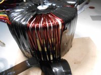
My newly developed theory is; what if there is noise on the line, harmonics of the line frequency. This noise would not be affected by a DC blocker, I assume. By careful stethoscope examination, it appeared to me that noise source was the actual copper windings. When I finally took 'the plunge' and decided to peel the outer wrapping, I found that the coils where simply wound on the core and held in place by tension, such as it was. My Yamaha P2200 has an (epoxy) encased toroid. My Phase Linear 700's have (varnish) dipped windings. These amps are quite. I have learned here about core saturation, but sensing that the sound was coming from the winding, I had a hope that dipping this transformer would help. The inner core lamination was inaccessible for stethoscope probing.
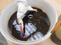
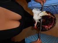
At the risk of redundancy, I will attach some photos of my 'dipping' process. It took 20 dips in Electrical grade varnish before I had the nerve to power it up and hear my results. I can honestly tell you that the transformer noise issue has been COMPLETELY resolved.
At the risk of redundancy, I will attach some photos of my 'dipping' process. It took 20 dips in Electrical grade varnish before I had the nerve to power it up and hear my results. I can honestly tell you that the transformer noise issue has been COMPLETELY resolved.
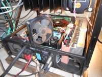
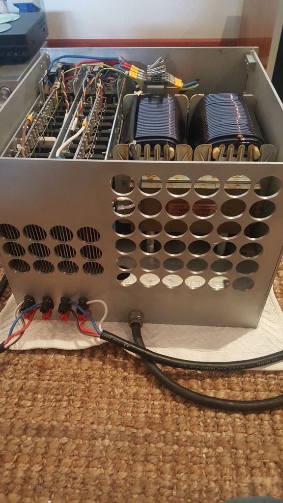
Here is my Baby with the cover off (photo below). The fan was easily removed, I did even have to lug the 80 lb monster out of the rack!
Speaking of monsters, and at the risk of high jacking the thread (briefly), can anyone explain why McIntosh amplifiers are so revered? It seems that even the solid state designs use output transformers, I don't understand the benefit.
Thanks again everyone.
Speaking of monsters, and at the risk of high jacking the thread (briefly), can anyone explain why McIntosh amplifiers are so revered? It seems that even the solid state designs use output transformers, I don't understand the benefit.
Thanks again everyone.
Attachments
Hi PeterS
Mine is in fact not a toroid but I guess that is irrelevant. Another member who I was chatting to offline suggested the blocker as I told him my tranny was noisy
It is not audio grade but very well made. Flat copper wound and was dipped. It has an air gap between prim and sec to.
The blocker is part of a massive EMI filter and quite a few other thing all on on PCB so that is why it is taking so long. I will take a pic just for fun
Mine is in fact not a toroid but I guess that is irrelevant. Another member who I was chatting to offline suggested the blocker as I told him my tranny was noisy

It is not audio grade but very well made. Flat copper wound and was dipped. It has an air gap between prim and sec to.
The blocker is part of a massive EMI filter and quite a few other thing all on on PCB so that is why it is taking so long. I will take a pic just for fun
Oh and you are worried about your fan. Mine only comes on at 35 deg and then low speed idle. At 40 it runs flat out but that would never happen during a movie and if it did you would probably be deaf or not worried. I have adjusted my quiescent current to fairly low and this helps to run a bit cooler. I doubt you could get a commercial amp to go lower in your case though.
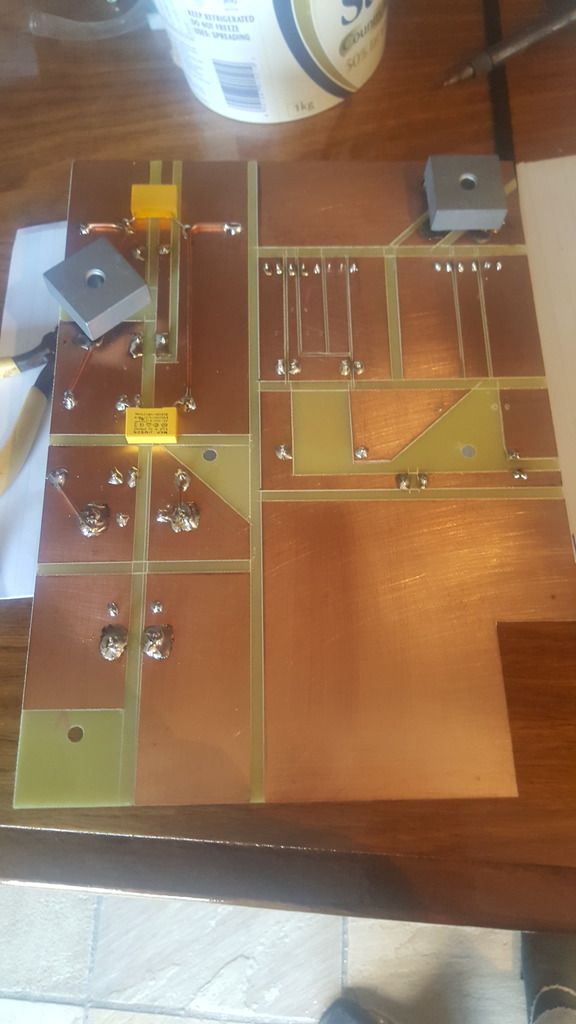
OK the blocker, and yes that one cap is in wrong but already fixed
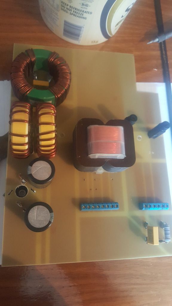
I am still busy with this board
OK the blocker, and yes that one cap is in wrong but already fixed

I am still busy with this board

toroid transformer have a continuous strip for the laminations. The "no joins" lamination makes for a very efficient flux circuit. It is easily overloaded. That results in excessive current and excessive noise when the operational conditions stack up against it..............Mine is in fact not a toroid but I guess that is irrelevant. Another member who I was chatting to offline suggested the blocker as I told him my tranny was noisy
................
Rcore have a similar jointless flux circuit to a toroid. I would expect them to be less tolerant of mains DC.
EI & Ccore have joints in the flux route. Those joints are never perfect and the extra flux resistance makes the core less suceptible to overloading. One gets a bit less noise.
Last edited:
Well to be honest I am really hopeful but if there is no improvement then I will just consider it a preventative measure. Same as the filter for that matter. Fortunately I have space to waste and the added mass is small in comparison to the total.
I suspect changing the mounting of the transformer would help a great deal but that is somewhat more difficult to implement then a simple bridge and 2 caps.
I will be sure to post my results
I suspect changing the mounting of the transformer would help a great deal but that is somewhat more difficult to implement then a simple bridge and 2 caps.
I will be sure to post my results
Hi M109R;
When I read "The amp modules are 2 x ESP P117 1K5watt each.", my curiosity was peaked! I Googled ESP and found that these are Class D output module PCB's(?)
I am very curious about your project. Is this amp for sub-woofers or full range speakers?
My background was on-the-job training and some electronics repair in theatre sound. Other members here would be the source for engineering info, however, I would like to make a suggestion that lead me in the direction of my solution. I used a thin wooden dowel (1/4 inch, whatever) as a stethoscope to locate the exact noise source. (one end pressed to my outer ear (pinna)). Is it one winding or the other, a particular area of the lamination, etc. You may have tried this but, have you tightened any through-bolts that hold the laminations together? Also, and I'm only making wild guesses here, but if the windings were dipped, THEN assembled to the core, could that interface be a noise source?
Is this noise continuous, or does it vary with time of day, fluctuations in line voltage, use of appliances in the house?
I may now ruffle a few feathers, but the DC blocker with 2 diodes in series would present a 1.4 V drop to the line voltage at high current. Would the entire full load current not exceed the ripple current capacity of the caps? That, combined with the line loss in your branch cct., might be an issue for a fanatic...I might have to retract this last paragraph!
1500 Watts RMS! into 8 ohms? Wow! I want this! I could not find that particular board on the Elliot website. Do you have more info? What is the B + and - Voltage?
Hi Peter
There is no board available on this ESP design. Rod Elliot published the design as an April fools joke but it really does work. There are some threads on here re the build and what you need to do to make it work. Ruffles feathers so be warned.
Thanks for the advice on trying to source the hum in the traffo. My mounting is something that could do with experimentation but at 46 kilos is not the kinda thing you hang by the windings and dip in varnish. It is also not a simple task to pull the thing out of the case so I leave it be.
Read your private message!
I may now ruffle a few feathers, but the DC blocker with 2 diodes in series would present a 1.4 V drop to the line voltage at high current. Would the entire full load current not exceed the ripple current capacity of the caps? That, combined with the line loss in your branch cct., might be an issue for a fanatic...I might have to retract this last paragraph!
As far as I understand and I could be wrong here, the highest voltage which could be presented across the two caps would be 2 x 0.5 volt. With a combined reactance of 0.9R the most current through the caps would be about 1 amp before the bridge takes over. Well within the ripple current of any reasonable 6800uF cap. So the max volt drop would be only 1 volt from this circuit. Hardly an issue.
The Xc impedance presented by a correctly sized capacitor should be in the milli-ohms region. Probably less than the cap's ESR.As far as I understand and I could be wrong here, the highest voltage which could be presented across the two caps would be 2 x 0.5 volt. With a combined reactance of 0.9R the most current through the caps would be about 1 amp before the bridge takes over. Well within the ripple current of any reasonable 6800uF cap. So the max volt drop would be only 1 volt from this circuit. Hardly an issue.
The current passing through the DC blocking capacitor could easily exceed the ripple rating. And the smaller you make the capacitor the worse I think this gets.
If only 1Apk were passing through the capacitor, then the rms value of that could be between 100mArms and 300mArms.
The power being delivered to the transformer would then be in the range 23VA to 69VA. Take off an allowance for transformer efficiency at this low pulsing current and you may have only 5W to 30W at the equipment supply rails. Is that even enough to meet quiescent current and bias requirements?
Last edited:
The Xc impedance presented by a correctly sized capacitor should be in the milli-ohms region. Probably less than the cap's ESR.
The current passing through the DC blocking capacitor could easily exceed the ripple rating. And the smaller you make the capacitor the worse I think this gets.
I still do not fully understand but my calcs are right 6800uF at 50 Hz is 0.468R
If is was much lower than 0.1R then that may be an issue, but then that capacitance would certainly be 4 x larger and have a much higher ripple rating?
Why is low ESR an issue? Are we not blocking DC and reactance the only parameter?
Just asking because I do not fully understand
Current passing ESR has the I²R heating effect.
It is this heating effect that eventually destroys your electrolytic. It is the ESR that is dominant in determining the ripple current rating.
A short period pulsing current has more heating effect than a sinusoidal AC current of the same rms value.
The primary current into a transformer feeding a capacitor input filter is a pulsing current where Ipk is anywhere from 3times Irms to 10times Irms.
It's Irms that feeds the transformer for effective power input.
Go back to the beginning and read the whole Thread. there are many Members here contributing to how and why.I still do not fully understand.............
Worth reading post59 where I am being corrected for my misunderstanding. Unfortunately he does not go on to explain where I have gone wrong. He justs restates the DC component.
Current passing ESR has the I²R heating effect.
It is this heating effect that eventually destroys your electrolytic. It is the ESR that is dominant in determining the ripple current rating.
A short period pulsing current has more heating effect than a sinusoidal AC current of the same rms value.
The primary current into a transformer feeding a capacitor input filter is a pulsing current where Ipk is anywhere from 3times Irms to 10times Irms.
It's Irms that feeds the transformer for effective power input.
OK I went back to the data sheet: 6800 uf 50 volt has ripple current of 3.94 volt at 120 Hz. The factor for 50 Hz is 0.9 so that I think brings it down a bit.
Still searching for the ESR...
Thanks
Last edited:
- Status
- Not open for further replies.
- Home
- Amplifiers
- Solid State
- Toroidal Transformer Noise