I use LM35 too, but analog regulation for the fan. The circuit is simple, and the ideas comes from Crest. 1/2 LM358+LM1117. Standing fan, up to 50C, than starting up, and increasing the speed. Maximum speed at 70C.
Sajti
Sajti
Hi Jwilhelm; If I were to use an additional pwm controller (thank you for your offer, I know you are not that far from me, I have an independent 24 V supply. It is an addition component, but I prefer it to modifying the amp further to extract the power source.
Sajti has raised my hopes regarding modifying the analogue fan control pcb to keep the fans off until 50 degrees C is reached. This would be my ideal solution. (perhaps I could adjust that threshold (maybe 40 or 45?)----now I'm getting fussy!
In any case, Sajti, would you have more info on this fan control that you suggest?
The fan control PCB uses three LM317T (voltage regulators). I have the schematic set for the Crest amplifier but it is too large to post here. I am at hennioriginals@gmail.com if anyone is interested in a copy.
Thanks Djk, I will look into just changing the fans also, but ( and I am just assuming) that a quieter fan may have a lower maximum CFM capacity, a mod to the fan control would be ideal (keeping the fans off or very slow until a certain temp)
The stock fan is about 100CFM and 45dB
4710KL-05W-B30-E00 NMB Technologies Corporation | Fans, Thermal Management | DigiKey
This fan is about 10dB quieter and 88.2CFM
The Crest CKS series have the fan off until the sinks hit 55°C or so, they seldom turn on for home hi-fi. The CKS 1600-2 is 1450W per channel.
4710KL-05W-B30-E00 NMB Technologies Corporation | Fans, Thermal Management | DigiKey
This fan is about 10dB quieter and 88.2CFM
The Crest CKS series have the fan off until the sinks hit 55°C or so, they seldom turn on for home hi-fi. The CKS 1600-2 is 1450W per channel.
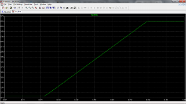
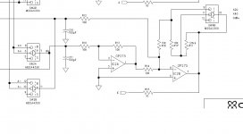
I put the fan circuit into the simulator. The result is, that the fan running about half speed continously up to 22-23C, than speeding up, and reach the maximum speed at 80C.
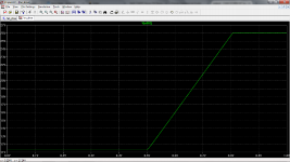
My modification keep the half speed running up to 50C, and reach the maximum at 80C. You need to add one more resistor, and replacing another one.
Sajti
My modification keep the half speed running up to 50C, and reach the maximum at 80C. You need to add one more resistor, and replacing another one.
Sajti
Attachments
Hi djk;
I'm beginning to think that replacing the fans would be the slickest solution. Thanks for that substitution suggestion. It seems to be ideal, a 10 db reduction would make things acceptable, and there would be minimal changes to the amp required. My lazy streak is showing but I hope I can swap fans without having to remove the output modules (and the infamous toroid).
I have a Crest 8001, that I completely disassembled for cleaning, and found that the fan was one of the last components that could be removed...
Attachments
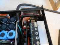
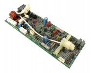
The above photo is the CA-18, looks like a tight squeeze , but hoping the fans will get past the heat sinks. First I have to pull the 80 lb monster out of the rack!
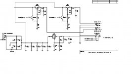
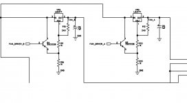
Hi sajti, I have tried to copy the fan control schematic from the complete pdf. Would you have a suggestion as to how this circuit could be modified to reduce the fan speeds?
The fan control PCB is also visible in the above photo, it is vertically mounted in front of the light blue power supply caps. Looks like a project, just to get access!
Attachments
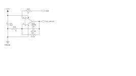
Hi sajti; This is the the IC 2A on my pre-amp pcb. It appears to be a signal amp rather fan control or am I looking in the wrong place?
You are on wrong page 🙂
Try to find the picture part I attached. It's on page 5 in the CA18 schematic, downloaded from crest audio homepage.
Sajti
Hi sajti; This is the the IC 2A on my pre-amp pcb. It appears to be a signal amp rather fan control or am I looking in the wrong place?
What You mean, is the input pcb.
Sajti
Thanks sajti;
I see it now. I have to confess that I am a little nervous about modifying this pcb. I am a little afraid of this amp, given the high power levels. Is there a manual or drawing that would show the component layout on the pcb?
Thank you for that picture, I see that Crest was kind enough to print the component numbers on the non foil side of the pcb. I did not notice this, the last time The cover was off! Did you take the above photo?
djk;
I see that NMB makes an even quieter fan (27 db @ 63.5 cfm) It is my nature to take things too far (we are taking about a 1000 W /ch into 8 ohms, bass amplifier) but would there be any draw backs to using this fan (4710KL-05W-B10) ?
As mentioned, this amplifier will only see brief passages of hard use before the wife shuts me down!
Attachments

Hi Peter,
the picture comes from the net. I used CA18, repaired it, but never owned. I understand Your point, that don't want to change the pcb. Replacing the fan has low risk. Thermal protection will shut down the amp, if the new fan is not strong enough.
Sajti
the picture comes from the net. I used CA18, repaired it, but never owned. I understand Your point, that don't want to change the pcb. Replacing the fan has low risk. Thermal protection will shut down the amp, if the new fan is not strong enough.
Sajti
Last edited:
Noisy UI
Sorry to barge in here but I noticed this thread and since I am in the process of building a DC blocker / EMI filter I thought I may get some opinions, impressions, results.
All I am really concerned about as was OP is whether the DC blocker is up to the task of a large PSU.
Backround: My traffo is a UI of about 6KVA and feeds 110 0 110 to the 2 rectifiers and 40 000 uf 250 volt capacitance. The amp modules are 2 x ESP P117 1K5watt each.
The blocker is 2 x 6800 50v and 50 amp bridge, my mains is 230 volt. I dont want anything to blow up and is this sufficient for such a load?
Mainly I just persevere to make the traffo quite on low demand such as under 1 amp draw for low level listening.
"I see that NMB makes an even quieter fan (27 db @ 63.5 cfm) It is my nature to take things too far (we are taking about a 1000 W /ch into 8 ohms, bass amplifier) but would there be any draw backs to using this fan (4710KL-05W-B10) ?
As mentioned, this amplifier will only see brief passages of hard use before the wife shuts me down! "
You may well be OK for hi-fi use.
I was just trying to find the highest CFM vs noise.
As mentioned, this amplifier will only see brief passages of hard use before the wife shuts me down! "
You may well be OK for hi-fi use.
I was just trying to find the highest CFM vs noise.
calculate the capacitor impedance @ mains frequency and use that to determine the maximum peak current the capacitor can pass to the transformer primary without the diodes starting to turn on.Sorry to barge in here but I noticed this thread and since I am in the process of building a DC blocker / EMI filter I thought I may get some opinions, impressions, results.
All I am really concerned about as was OP is whether the DC blocker is up to the task of a large PSU.
Backround: My traffo is a UI of about 6KVA and feeds 110 0 110 to the 2 rectifiers and 40 000 uf 250 volt capacitance. The amp modules are 2 x ESP P117 1K5watt each.
The blocker is 2 x 6800 50v and 50 amp bridge, my mains is 230 volt. I dont want anything to blow up and is this sufficient for such a load?
Mainly I just persevere to make the traffo quite on low demand such as under 1 amp draw for low level listening.
Ask yourself the question:
Will my transformer primary ever demand more current than the capacitor can pass?
Thanks AndrewT
So assuming I have +/- 1 ohm impedance the bridge should take over at around 1.5 amp?
That would be fine I think.
So assuming I have +/- 1 ohm impedance the bridge should take over at around 1.5 amp?
That would be fine I think.
I get 0.47ohms for Xc @ 50Hz for 6800uF
Are your 6800uF in series, or in parallel?
Is your diode turn on voltage = 500mVpk, or to 1Vpk for two in series?
Are you beginning to see that post355 was impossible to answer?
Are your 6800uF in series, or in parallel?
Is your diode turn on voltage = 500mVpk, or to 1Vpk for two in series?
Are you beginning to see that post355 was impossible to answer?
I get 0.47ohms for Xc @ 50Hz for 6800uF
Are your 6800uF in series, or in parallel?
Is your diode turn on voltage = 500mVpk, or to 1Vpk for two in series?
Are you beginning to see that post355 was impossible to answer?
Oops sorry yes they are in series opposed and I just took a guess at 750mV, it may be less but at least now I understand the analogy. Due to my PCB tracks I am limited on capacitor current so that is fine and what I was hoping for. I dont care if the DC gets through when the amp is drawing over 1 ampere current because I will then not hear the hum over the music SPL.
I will look at post 355, I jumped in a bit late and didn't go through the whole thread.
- Status
- Not open for further replies.
- Home
- Amplifiers
- Solid State
- Toroidal Transformer Noise