Hi Folks;
Because there seems to be no service 'manual' for the Crest amps, other than schematics, I think it wise that I improve my knowledge base rather than bombard this thread with dumb questions.
I have found a book "Audio Power Amplifier Design" 6th edition, by Douglas Self, available on line. A brief 'skim' looks like it would be extremely beneficial. Could anyone suggest another book that also touches on Class H design?
Unable to resist the urge to skip ahead, I am sensing that there is some need for clarification (at least for me) regarding the differences between Class G and H. Anyway, back to more reading before I get my hands dirty.
......However, about dirty amplifiers, (and I will approach this subject cautiously!), I have been advised by you folks to clean my Crest 8001 before further testing. Both of my Crest amps have 2 PCB's piggy-backed with long pin connections between them. It was mentioned by someone here (sorry for not crediting), that these connectors are rarely an issue. To anyone familiar with this Crest design, should I separate the 2 PCB 'decks' or simply remove the output modules from the amp for cleaning?
Thanks again all, Peter in Canada
D.Self's Power Amplifier book is very good. But D.Self is very much a ClassAB for BJTs. He does a bit on ClassA.
His treatment of other Classes is little more than "they exist" and similar of mosFETs.
If you want ClassG and/or H you need a more specialised book/website.
His treatment of other Classes is little more than "they exist" and similar of mosFETs.
If you want ClassG and/or H you need a more specialised book/website.
Thanks Andrew and everyone;
I will look for a book that is more Class G and H specific. I think Douglas Self's book will be a huge benefit for the moment.
Thanks jwilhelm and all who advised me to disassemble the Crest 8001 befor further testing. As mentioned, the screws for one output module are 'finished', but so far, the dirt is to thick to see where the repairs have been made.
I have attached photos, just for giggles.
Attachments
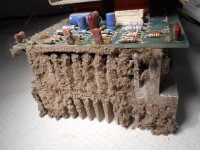
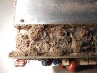
As mentioned, the previous owner said it was 'stuck in protect' after the dog chewed through a speaker wire. I (foolishly) connected small speakers and a signal generator after bring it home. It worked! The Volume pots where not even noisy!
Attachments

Nice pictures! I will be happy if You show more!
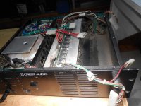
Anyway the last maintenance was long time ago....
Sajti
Anyway the last maintenance was long time ago....
Sajti
Hi guys;
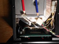
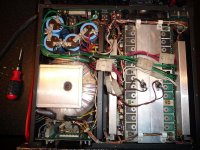
I will have to study the schematic, but can anyone tell me why there are two unconnected plugs inside this amp? (Both channels worked, anyway!) Connectors are indicated by the pencils.
I should have started another thread, this is the Crest 8001. I'm keeping myself amused, while the varnish dries on the toroid for my Crest CA-18.
BTW; Dip 17 for the CA-18, and sounding more 'solid' with every dip. I promise to put the power to it after dip 20!
Attachments
Hi guys;
I will have to study the schematic, but can anyone tell me why there are two unconnected plugs inside this amp? (Both channels worked, anyway!) Connectors are indicated by the pencils.
Interesting, as Crest use the red color for +rail, and green for the -rail. Disconnected this connector means missing power from one card...
Sajti
Hi Sajti;
But....Both channels worked on this amp with those connectors not connected. Could there be an option that this amp did not have?
But....Both channels worked on this amp with those connectors not connected. Could there be an option that this amp did not have?
Hi Sajti;
But....Both channels worked on this amp with those connectors not connected. Could there be an option that this amp did not have?
Hi,
absolutely no.
There are 2 ideas come to my mind:
1, Look around in the amp, and try to find empty socket, within the range of the loosing connectors. And check on the schematic if You find.
2, Search for pictures about the 8001. This is very popular amplifier, and there are many of them still in use. Maybe You can find picture, where this connectors are connected to somewhere.
Sajti
ATL Hi-Fi DC & Ripple Blocker x4 ME (aka “Maty Edition”)
So the four boards are connected in series and the last one to the four receptacles. The fact that the receptacles are also four is then independent on the number of boards. Is this correct?
Roberto
No.
This is a DC block to help reduce transformer saturation, or near saturation, due to unequal waveform that makes the transformer draw excessive primary current and usually becoming noisy (a growl).
And the DC block does not need to be in the Hot/Live line.
It works just as well in the Neutral Line and even works between the two windings of a series connected dual primary.
The slight advantage of locating the DC block in the Neutral is that it operates at near Neutral voltage. The voltage difference between the Chassis and the DC block is much lower (when the mains socket outlet is wired correctly).
Add a little capacitor and a resistance in parallel and you get the ATL DC blocker.
You are mentioning that it works just as well in the Neutral Line. How about putting one on the L and one on the N instead of placing two in series as in Mati's constructions? Would it be more effective?
Roberto
Splitting the DC blocker into a Live half and a Neutral half is no more effective.
I saw a split version linked on this Forum a few years ago and I'm pretty sure I commented on it at the time.
I saw a split version linked on this Forum a few years ago and I'm pretty sure I commented on it at the time.
Splitting the DC blocker into a Live half and a Neutral half is no more effective.
I saw a split version linked on this Forum a few years ago and I'm pretty sure I commented on it at the time.
Thank you. Hence, putting gone on L and one on N would be essentially like putting them in series, both on L or on N.
But you also said "The slight advantage of locating the DC block in the Neutral is that it operates at near Neutral voltage - The voltage difference between the Chassis and the DC block is much lower " does this means that it would be slightly more effective or that components like the capacitors would be stressed less and thus the circuit would have higher longevity?
Also, what is the role of the similar circuit with the diodes and the capacitor between ground and central power supply ground in the Bryston circuit?
Roberto
Only that the electric shock you would get from the Neutral connected could be much lower if the mains house wiring has been correctly installed.
There is no performance benefit.
Remember that polar electrolytic capacitors need to be used in series in back to back arrangement to work with this AC current. And they need to be very high value to pass the peak currents that are the result of using a capacitor input filter.
The bypass diodes should only turn on during start up and during an abuse incident.
Hi Sajti;
Thanks so much for your help, I googled images for the 8001, and found a picture with those 2 connectors open ended!
I will examine the schematic to see if they are 'test points" or what?
Attached is another 8001 from the web. Thanks everyone for your input. I know I have wondered of the initial point of this thread; the noisy toroid in a Crest CA-18.
Thanks, Peter. Canada will be a lot louder when I get these two amps back together!
Attachments
That plate on the top of the transformer securing bolt MUST be electrically insulated.
Is your version built with, or without that plate?
Is your version built with, or without that plate?

I built Rod Elliott's dc blocker circuit for my F-5, it has 500VA toroid and it was growling like a hungry wolf. Noise was mechanical, periodic. Every 15sec, 5-6sec loud growling. It was audible within 4-5meter.
I used 2*33000uf 16V philips caps with 35A bridge. I can still hear it, but it was reduced %80 percent and time period has changed too.. Now every 20sec, 1-2sec faint, almost inaudible growl. Also toroid was reaching 70C heat in 30min, now after 1 hour it is 40-45C...
I used 2*33000uf 16V philips caps with 35A bridge. I can still hear it, but it was reduced %80 percent and time period has changed too.. Now every 20sec, 1-2sec faint, almost inaudible growl. Also toroid was reaching 70C heat in 30min, now after 1 hour it is 40-45C...
Hi folks;
Sounds like there was definitely DC in the AC line, starbender.
Regarding my 'loose' connectors in the Crest 8002, I just read in the owners manual that there is an optional 2 speed AC fan. Could these connectors be for a fan controller?
Sounds like there was definitely DC in the AC line, starbender.
Regarding my 'loose' connectors in the Crest 8002, I just read in the owners manual that there is an optional 2 speed AC fan. Could these connectors be for a fan controller?
Hi.
to starbender:
Did you ever tried two diodes back to back instead the bridge? The reason it is that by using the bridge you have 2 diode back to back that will raise the voltage across the two diodes. Just a thughts/suggestion. I had the same problem and using only 2 diodes back to back completely eliminated the humming coming from the toroid transformer.
- Status
- Not open for further replies.
- Home
- Amplifiers
- Solid State
- Toroidal Transformer Noise