I think Rod's snubber would be the better option.... a smart bloke like Rod would normally choose the better option.
Also, when the adjacent primary is on, the induced voltage in the other primary would be opposite to when it was conducting. If you put a diode accross it it would be effectively shorting out a winding which is never good.
Also, when the adjacent primary is on, the induced voltage in the other primary would be opposite to when it was conducting. If you put a diode accross it it would be effectively shorting out a winding which is never good.
fr0st said:Also, when the adjacent primary is on, the induced voltage in the other primary would be opposite to when it was conducting. If you put a diode accross it it would be effectively shorting out a winding which is never good.
thanx allot man ! i dindt think of it 🙄
Just a quick question... (not worth starting a new thread)
Is it alright to use a half wave rectifier on each secondary (diode reversed on the negative rail) ?
I'd assume it would create a larger current peak while charging the cap since they would only be charged by one secondary rather than both?
Normall I would use a full bridge but I have quite large dual diodes (200A each diode) which would be a pain to cut in half.
Is it alright to use a half wave rectifier on each secondary
then whats the point making a push pull circuit?
anyways
i have desided to use the UC2528AN chip instead of the more common SG3525 because it got 2A peak output current and a current limit option
i'm thinkin of a way to limit the output current in case of short circuit , do u think the next circuit will work good? (sorry for a bad pic , made it with paint 🙂)
soon the full schematic 😀

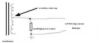
This only senses the difference in current consumption between rails
Other ideas :
- A current transformer on the primary or secondary side [this is tricky and requires an additional small ferrite core but it's very elegant and precise]
- Measure and amplify the voltage drop on some thick circuit track or wire that carries all the primary current
- Put an LC filter on the primary side [for ripple filtering] or in the secondary side [for output regulation] and integrate the instantaneous voltage difference across the inductor to get the instantaneous current flowing through it [This is very tricky but works. I succesfully use this method to sense the current through the output inductor in a 230V to 14.4V 72A SMPS prototype intended for car audio exhibitions]
- Measure the voltage difference between drains and sources of the set of MOSFETs that are conducting [it's complex to implement since the measuremt should be disabled before turning off each set of MOSFETs and enabled after they are again fully turned on
Wow! .... can't read thro' 17 pages .....
See my (warning) note about SMPS for audio on the Chip Amp forum - it's not far!
JohnT
See my (warning) note about SMPS for audio on the Chip Amp forum - it's not far!
JohnT
more problems
i'm stuck again 🙁
i got very large voltage spikes at the secondary side of the transformer, those spikes have killed my diodes !
does this got something to do with the transformer ? something wrong with the windings?
i'm stuck again 🙁
i got very large voltage spikes at the secondary side of the transformer, those spikes have killed my diodes !
does this got something to do with the transformer ? something wrong with the windings?
Re: more problems
your transformer is doing exactly what it's supposed to do -- transforming -- thus if the turns ratio is 1:2 and you have an 18V spike, it comes out 36V on the other end -- but it's more complicated than that == the transformer has to be "nicely" wound -- not scramble wound with poor coupling, every trace on the board is an inductor which stores energy momentarily -- trace widths in paths which may not seem to conduct a lot of current can be problematic, you have to get the compensation values correct ==
you should also use inductors on the secondary side of the transformer -- the values will depend on the switching frequency, load etc. -- time to pick up a textbook like Pressman's "Switching Power Supply Design"
switch-mode power supply design is a big "linear programming" problem -- optimizing this, minimizing that, trying to steal the last oink out of the pig -- for the DIYr it isn't quite an insurmountable task, but certainly daunting. The point i wish to make is that efficiency and energy conservation rank high on the outputs of the LP problem -- and herein lies the difficulty for the DIYr -- someone at Vicor, PowerOne or Tyco etc. have boundless resources to tackle problems and they wind up discussing noise all day long.
if you as the DIYr will make a tradeoff for lower efficiency you can build a quieter, less transient prone switching supply -- this is why I will recommend the slew-controlled switcher chips from Linear Tech over the SG3524.
sss said:i'm stuck again 🙁
i got very large voltage spikes at the secondary side of the transformer, those spikes have killed my diodes !
does this got something to do with the transformer ? something wrong with the windings?
your transformer is doing exactly what it's supposed to do -- transforming -- thus if the turns ratio is 1:2 and you have an 18V spike, it comes out 36V on the other end -- but it's more complicated than that == the transformer has to be "nicely" wound -- not scramble wound with poor coupling, every trace on the board is an inductor which stores energy momentarily -- trace widths in paths which may not seem to conduct a lot of current can be problematic, you have to get the compensation values correct ==
you should also use inductors on the secondary side of the transformer -- the values will depend on the switching frequency, load etc. -- time to pick up a textbook like Pressman's "Switching Power Supply Design"
switch-mode power supply design is a big "linear programming" problem -- optimizing this, minimizing that, trying to steal the last oink out of the pig -- for the DIYr it isn't quite an insurmountable task, but certainly daunting. The point i wish to make is that efficiency and energy conservation rank high on the outputs of the LP problem -- and herein lies the difficulty for the DIYr -- someone at Vicor, PowerOne or Tyco etc. have boundless resources to tackle problems and they wind up discussing noise all day long.
if you as the DIYr will make a tradeoff for lower efficiency you can build a quieter, less transient prone switching supply -- this is why I will recommend the slew-controlled switcher chips from Linear Tech over the SG3524.
...I am not sure, but it sounds like you are facing issues with some parasitic inductances...
Are these peaks only destructive at high load?
How high (i.e. 100V ?) and how long (i.e. 100ns ... 300ns ?) are these peaks?
Just to understand correct:
You are observing high voltage peaks at the diodes of the secondary rectifier. Polarity of these spikes is in blocking direction of the diodes.
Right?
yupChocoHolic said:Just to understand correct:
You are observing high voltage peaks at the diodes of the secondary rectifier. Polarity of these spikes is in blocking direction of the diodes.
Right?
the spikes are 70 to 200 volts , it changes when i play with the frequency , the spikes are generated when no load is connected
(the normal Vout is ~35V)
the resistor -capacitor network connected to the primary is not helping

sss said:
yup
the spikes are 70 to 200 volts , it changes when i play with the frequency , the spikes are generated when no load is connected
(the normal Vout is ~35V)
the resistor -capacitor network connected to the primary is not helping
javascript:smilie('
 ')
')javascript:smilie('
')NEVER HOOK UP AN SMPS WITHOUT A LOAD !!!!!!!!!!!!!!!!!!!!!
the simplest demonstration would be to run through the math of a boost regulator -- the value of the inductor is inversely related to the current flowing to the load.
i put this spreadsheet together -- http://www.tech-diy.com/smps_xfmr.xls
for calculating the various values -- if you change the red box "load" you can see how the demanded inductance of the transformer changes.
...hm, no load is often critical...
If this is the reason then you would not only see high
voltages at the transformer, but also the output voltage would
be high! Did you check this? If your output voltage is also much to high, then the missing load is probably the reason (some of the XFR magnetization energy is always transfered and can pump up the output caps, if there is absolutely no load).
Also an inductor behind the rectifier (as in the LT application note) is helpful to reduce the current ripple and avoiding current peaks.
But I do not think that the absence of that inductor is the reason for your voltage spikes.
Do you observe the voltage spikes also if a load (say 10% of full power) is connected?
Do the peaks happen at the moments, when the MosFets are turned off?
The peaks are getting higher if the frequency is lower?
May be you require a similar snubber as on the primary also on the secondary. ....but somehow I am wondering, why this should be necessary.... because a centertappet secondary winding, with a full bridge rectifier (all 4 diodes fast!), should allow to go without snubber on the secondary (if some small minimum load is applied to avoid pumping up the output caps by the unavoidable transfer of some magnetization energy from the XFR)....
I will keep thinking about that all.
Bye
Markus
thanx guys !
ChocoHolic : the output voltage is high , thats the problem 🙂 my diodes rated at 100V when the output should be +-35V , i cant get fast diodes with higher voltage rating .
the load supposed to be the amp , but i think it supposed to work without a load , am i wrong ?
i guess feedback is not gonna help eather
i'll try connecting small load tomorrow
Hi tripple s!
No load condition is critical because of the following:
-You are driving the transformer in a push pull configuration
and some dead time.
During the time when a MosFet is turned on, the transformer is storing energy. Magnetization energy. As the flux in the core is increasing by the applied time voltage product also the stored energy is increasing.
(Energy is increasing by the square of the time voltage product).
Then you turn off the switch. The transformer is now starting to feed back the stored energy. Some portion it feeds back to the primary, but also some portion to the secondary. The rectifier is transfering this energy to the output caps and clamps the voltage at the transformers volatge to the outut voltage.
If there is no load at the secondary, then the transfered energy is pumping up the output capacitors. You cannot avoid this.
IMHO this push pull topology would only be able to handle a no load condition, if there would be a feedback regulation that could decrease the switching duty cycle down close to zero (preferably without increasing the frequency).
So my proposal is: Just use some load.
For an smps to supply an amp you do not need a zero load proof design. The amp which you want to supply will consume enough by it's idle current, even without music signal.
If you still have that high voltage peaks at some load, then we must start thinking again....
Bye
Markus
I forgot to explain, that there are two energy storage mechanisms in that XFR.
-Energy stored in the leakage inductances
-Magnetization energy
The energy in the leakage inductances is mainly depending much on the load current and the XFR's coupling.
An ideal transformer with a coupling of 1, would eliminate this.
The magnetization energy is depending on the applied voltage time product and the XFR's inductance. In order to make it zero, we would need an indefinitely high inductance.
...already hearing your question: Why HIGH inductance?
The magnetization energy can also be seen in the in input currents of the transformer. The input current contains a load related portion and the magnetization current. The magnetization current is linear ramping up and down and only related to the applied time voltage product and the XFRs inductance. The steepness of it's ramping is described by the following formula:
delta I / delta t = U / L
Here you see that a smaller inductance will cause a steeper ramping of the magnetization current. If it ramps up steeper then you will have a higher magnetisation current in the moment, when you turn off the MosFet. The stored energy in an inductor is :
Energy = 0.5 x L x I^2
Example with double inductance:
==> (half current)^2 x double inductance = half energy ......
Bye
Markus
thanx ChocoHolic
i solved the problem !
heres what i have figured out:
i am using push pull config , i disconnected one side (one of the primaries) and there were no spikes at all !
so i think the problem is in the dead time area when one mosfet switches off and the other on . So my solution was to increase the dead time , the original duty cycle was 97-98% or so , i redused it to 90% (this is the duty cycle of the oscilator -more duty cycle=less dead time ) and the spikes have been redused 😀
one more important thing :
i have made a feedback loop and set the output to 45V .the normal Vout is suposed to be 35 volts so what the feedback does is making sure that Vout wount exceed 45V when no load is connected . when there is a load the voltage is below 45V (like it should be ) so the feedback is doing nothing 😀
i hope u can actually understand what i mean 🙂 , its a good idea , dont u think ?
Why is discussion about wire sizes (for primary and secondary) and discussion about snubbers don't come up until now? Is everybody just making small size car smps? These discussion should appear if someone has made huge Watt car smps.
I've got a big project ahead. Class AB power amp for driving car subwoofer. The audio amp voltage is +/-75V. But I wanted this car amp able to drive 1 ohm load (for bridged parrareled car subwoofer).
I've got 1cm2 Ae ferrite core. The pushpull smps will be working 30khz (60khz clock).
Due to skin effect theory, I have to use small size wires in parrarel.
1. What is the good wire size? I think about 0.8mm wire magnet in parrarel.
2. How many wires will be needed for primary? What is the calculation?
3. How many wires will be needed for secondary?
- Status
- Not open for further replies.
- Home
- General Interest
- Car Audio
- toroid for car amp smps