Hi.
I just saw this thread.
I have builded small smps with pwm. When I run this smps without pwm (50% duty cycle) everything is ok. Small spikes and practicaly no spikes with small load. But when I run this smps+pwm (using opto feedback) I get strane readings on scope.
I dont have camera so I draw image from analog scope.
Center tap of primari is conectet do GND of scope
1 image - 1st primary
2 image - 2nd primary
3 image - gate1
4 image - gate2
With red color is 50% duty cycle, with 50% duty everything is ok .
So ignore red lines.
So this is about 10-15% duty cycle .
Is this normal ?
Attachments
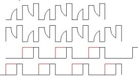
I see nothing wrong here, the core just resets itself showing a voltage pulse of similar width and opposite polarity after each switching pulse
You are not using coupled buck inductors at all on the secondary side, aren't you?
Using the traditional symmetric inductor-diode topology the transformer would be shorted from the secondary side during dead time [in case of continuous conduction] so flux resetting would happen only during the next pulse [still not a problem, each pulse resets and inverts the flux of the preceding pulse]
I agree and like the appearance of it. I see a ringing frequency relatively near that of the active transformer drive. This passive oscillation frequency would increase as the load on the secondary increases.
I have put together an Excel spreadsheet for my own use that evaluates toroid power handling, wire sizing, flux density, etc for the toroids I usually buy. It may not be perfect, but I think it gives a good estimate. Note that power handling changes with the desired max temp and flux density, so this may give slightly different power values than a chart you may have read gives, but it is more flexible to your application than a chart because the variables aren't static. I thought I'd let you all look at it/use it, if there is anything terribly wrong with it please let me know. Thanks!
download
download
Hi.
Eva : I use two separate inductors yellow/white from PC power supply after diodes on secondary before capacitors.
Well I hav few questions.
1) I'm using EE core from PC power supply, how is best to wind first primary or first secondary ? Now I have secondary first .
2) As Im using PWM, how much more turns on secondary can I put. What hapens if I have for example 4+4/30+30 turns and I'm regulating this with PWM to 37+37 volts.
3) How can I find best operating frequency for some core using oscilloscope.
Thanx .
For better coupling and lower leakage inductances I recommend sandwitching techniques
You may wind one seconary first, then both primaries [trying to use only one layer for each or bifilar winding] and then the other secondary, but this means both secondaries will show somewhat different electrical parameters. This may or may not be a problem depending on your application
To get matched secondaries you may try to wind half the turns of both secondaries first in a bifilar way, then wind both primaries using one layer for each or also in a bifilar way, and then wind the rest of the secondaries turns also bifilar
Bifilar means to wind two windings 'at the same time', ie: interleaved turns, so both use same wire lenght, show same DC resistance, have same leakage inductance and show nearly the same coupling to the rest of the windings. As a negative effect, bifilar winding increases inter-winding capacitance and may increase ringing
Another option that may generate still matched secondaries but less ringing due to lower inter winding capacitances, but maybe more stray magnetic fields due to external primary, is to wind half the turns of both primaries first in a bifilar way using one layer, then wind two secondary layers [one layer for each winding] and then wind the rest of the turns of the primaries also in a bifilar way
For your application I think you only need matched primaries, since each secondary provides current to both output rails alternatively
For output inductor, I recommend you use a coupled inductor, ie: wind output inductors for both rails on the same core [or stack of glued cores]. This enhances cross regulation in case of different load currents on each rail. Bifilar winding may enhance cross-regulation even more, but it's not required and it may cause ringing problems. Better to experiment and decide
You have to design this coupled inductor with a number of glued stacked iron-powder cores high enough and an inductance low enough to allow it to not run into deep saturation even at full load
PC PSUs tend to use low permeability iron powder materials and the number of turns and the size of the core of the output coupled-inductor are carefully choosen in a way it progressively saturates as current increases, so inductance reduces progressively with load and ripple current tends to be proportional to load instead of constant as it would be with an ideal inductor. This saves costs and space as it allows to use a small and cheaper iron powder core
The best way I've found to design these inductors is empirically, ie: trial and error, by measuring current [Y] versus time[X] plots with constant voltage pulses of controlled width applied [and time to reset the core between pulses]. The real inductance for a given current value then would be Vpulse * d(time) / d(current) or Vpulse / current_versus_time_slope
These graphs describe very well the behavior of an iron powder or a ferrite or iron gapped inductor as you know from them how exactly the core saturates. I generate these plots with a SG3525 whose pulse width and frequency are controlled with potentiometers [also jumpers for frequency range 1x/10x/100x], a 15V regulated supply with a big output capacitor [it has to provide the test current], a 60A switching MOSFET and some extra components [diode, power resistors of adequate value, etc...] for core resetting. I capture the plots with a digital storage oscilloscope to be able to measure slopes with calm after I turn-off the 'thing'
About the turn ratios, your circuit works exactly as a buck converter but transformer coupled so it follows all the laws of the buck converter. The steady state output voltage would be equal to input_voltage * turns_ratio * duty_cycle [assuming no losses]. You have to select the minimum turns ratio that allows to get the desired output voltage even with the minimum specified input voltage, taking into account maximum allowed duty cycle
Buck converters require also frequency compensation if you want to regulate them. This is acomplished by adding a zero and a then a pole after the existing pole [usually at a much lower frequency] of the error amplifier [everything depends on switching frequency and output RLC parameters]. Optocouplers are evil since they add poles and sometimes they are places at frequencies low enough to interfere with regulation. I can't give rules to accomplish frequency compensation since I tend to do it mostly empirically by simulating output filter bode plots, including series resistences of all components [very important], and adapting error amplifier bode plots to filter bode plots by hand]
can someone plz post some commonly used transistors for car smps , i cant find mtp75n06 over here 
sss said:can someone plz post some commonly used transistors for car smps , i cant find mtp75n06 over here
I don't think that one is recommended for new designs -- just check the parametric search engine at www.onsemi.com, or take a look at the data sheet for NTP75N06
sss:
Try to search cool devices by yourself. You have to look for >50V Vds and low Rds-on at the best price, also low capacitances and/or gate charges are useful. Some examples of manufacturers too look at are International Rectifier, Intersil, On-Semi, Vishay-Siliconix, etc...
I usually buy the cheapest devices I could find with good enough specs. For example, some months ago I bought a lot of 100 IRFZ48V for 100 euros because other similar devices were priced at up to 5 euros/each and IRFZ48V had pretty good specs for their price. I've used them to pass 80A [50% duty cycle and 18V Vgs] and still no one blows. The only flaw I've seen is about 300ns current tail when you turn off the device very quickly [gate discharge time < 100nS] but I think this phenomena is common in cheap MOSFETs
To select devices I think it's better to look at component dealers catalogs first, to see what switching MOSFETs they sell at what prices and then look for the specs of these devices and compare specs versus prices
why ??😉Eva said:Try to search cool devices by yourself
anyways
i checked at my local store and they say that they dont have those high current mosfets , the only thing i could find was MTP50N06 - its up to 42A , 60V , Rds(on) is 28mohm
max Vds(on) is 1.7V , its too high isnt it?
What's wrong with that mosfet?
Parralelling cheaper mosfets can almost equal the more expensive ones. Most likely thier cheaper than the NTP75N06 so you do get what you've paid for.
Also, a question for the experts, does primary side capacitance make a huge difference (after inductor and before)? Does it have a purpose other than rail stiffening?
Thanks
fr0st
input cap primary side
Without a schematic, I'm going to guess what you're asking. The inductor you refer to is, I believe, the filter choke connected to the input supply. You wish to know if a bulk capacitor on the primary side has a great effect, and whether it should be placed before or after the inductor.
I would strongly recommend the input capacitor, and it should be placed after the inductor. The bulk capacitance provides the ac ripple current demanded by the transformer primary when the FETs are switching. A large input cap located close to the primary provides the ripple current, so that the input current drawn from the battery/alternator is largely dc with a very small ac ripple. The benefit is lower voltage drop, I*R, and lower "I squared R" power loss. Without the cap, the large ac ripple current would be present on the input wiring. Voltage drop would increase due to inductance, as well as increased (I^2)*R losses due to skin effect. It must be located after the inductor so that large increases in current demand can be provided by this cap. I always use a cap on the input for any smps. I hope I've answered your question.
posted by fr0st
Also, a question for the experts, does primary side capacitance make a huge difference (after inductor and before)? Does it have a purpose other than rail stiffening?
Without a schematic, I'm going to guess what you're asking. The inductor you refer to is, I believe, the filter choke connected to the input supply. You wish to know if a bulk capacitor on the primary side has a great effect, and whether it should be placed before or after the inductor.
I would strongly recommend the input capacitor, and it should be placed after the inductor. The bulk capacitance provides the ac ripple current demanded by the transformer primary when the FETs are switching. A large input cap located close to the primary provides the ripple current, so that the input current drawn from the battery/alternator is largely dc with a very small ac ripple. The benefit is lower voltage drop, I*R, and lower "I squared R" power loss. Without the cap, the large ac ripple current would be present on the input wiring. Voltage drop would increase due to inductance, as well as increased (I^2)*R losses due to skin effect. It must be located after the inductor so that large increases in current demand can be provided by this cap. I always use a cap on the input for any smps. I hope I've answered your question.
sss:
In Spain, local stores usually don't have exactly what you want and they tend to have high prices. Look at internet stores, you may find higher current MOSFETs at the same price or cheaper than those old medium current MOSFETs available in your local store
In Spain, local stores usually don't have exactly what you want and they tend to have high prices. Look at internet stores, you may find higher current MOSFETs at the same price or cheaper than those old medium current MOSFETs available in your local store
Eva :
i can buy stuff from the internet only locally because my credit card is not international (i got no time to go to a bank and ask for a better one 🙄 )
this thread is talking about smps transformers , those are high freq transformers that using ferrite cores , toroid is just a shape
i can buy stuff from the internet only locally because my credit card is not international
(i got no time to go to a bank and ask for a better one 🙄 )it depends on what u are trying to makeDanyele82 said:What is the best material for toroid core?
this thread is talking about smps transformers , those are high freq transformers that using ferrite cores , toroid is just a shape
IVX :
Things are not available nor cheap everywhere. In the same european store I bought the IRFZ48V, IRF3205 were priced at 6.75 euro each without volume discount option. No doubt IRF3205 is a better device but at that price...
Things are not available nor cheap everywhere. In the same european store I bought the IRFZ48V, IRF3205 were priced at 6.75 euro each without volume discount option. No doubt IRF3205 is a better device but at that price...
can i use RURP3060 "RURP3060 30A, 600V UltraFast Diode, ... General description The RURP3060 is
an ultrafast diode (t rr <55ns) with soft recovery characteristics..." i have 20 pcs and i have some BYV29, BYW29,BYW80-150 witch one is better ?
Thanx,
😀
an ultrafast diode (t rr <55ns) with soft recovery characteristics..." i have 20 pcs and i have some BYV29, BYW29,BYW80-150 witch one is better ?
Thanx,
😀
Eva, it's so strange, 6.75!! unbelievable!! it's no joke?
http://www.efind.ru/icsearch/?search=irf3205

http://www.efind.ru/icsearch/?search=irf3205
- Status
- Not open for further replies.
- Home
- General Interest
- Car Audio
- toroid for car amp smps