I would say that they are ferrite, Iron powder usually comes with a color code, it's a shame though that you don't know the permeability of the material...maybe someone on the site could give you some pointers on finding it out.
I guess this is as good a place as any to ask about another power supply I am trying to fix. people tend to respond more here anyway. My friend brought me his amp. It works great on my bench after I replace the mosfets, but any time my friend pops the amp back in his car, it only lasts an hour or so before the mosfets explode.
This has confused me, because it works so nicely on the bench, checked the waveforms, everything looks great.
Digging deeper, though, I noticed that the inductor filtering the input from the +12V battery is shorted out on itself, so it's basically just a jumper. Is this minor, or is it the cause of the problem?
My thinking is that the inductor calms the instant inrush when the amp is powered on, and no inductor means blown mosfets. Sound reasonable?
imho i think that this inductor got nothing to do with it , this inductor is eliminating the switching noise so there wount be interference with other equipment .tennisballg said:My thinking is that the inductor calms the instant inrush when the amp is powered on, and no inductor means blown mosfets. Sound reasonable?
.
It could have to do with things like dash board temperature, speaker load, and 13.8v power in the car vs. 12 on the bench, among other things.
This has confused me, because it works so nicely on the bench, checked the waveforms, everything looks great.
It could have to do with things like dash board temperature, speaker load, and 13.8v power in the car vs. 12 on the bench, among other things.
sss:
This looks like a common mode filter so the toroid is probably made from high permeability ferrite
Anyway, It's easy to find out the optimum volts/(turn*Hz) value for any core by aplying constant voltage pulses of controlled lenght to a known number of turns and looking for saturation in the current waveform while progressively increasing pulse width [allowing the core to reset between pulses]. That kind of test is easier to perform with the help of some PWM IC like SG3525A, a switching mosfet and a clamping R and D network
 , most of the time ferrites are fragile
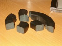
I am a power engineer and I wanted to get in on this forum. So posting this message will subscribe me. Also, I have some soft magnetic materials in my own stash that could be available if someone wants. I have some toroid ferrites, toroid MPP cores, Toroid High Flux MPP, and some Kool Mu. I have a boatload of the ferrites. If anyone is interested send and email and I will give you the information you need on the cores or on SMPS design. That's what I do! Check out my Class-T amplifier section with off-line SMPS for everyone to see.
http://www.diyaudio.com/forums/showthread.php?s=&threadid=6122
http://www.diyaudio.com/forums/showthread.php?s=&threadid=6122

i found a junk store where i can get those for 1$ 🙂
now i'm trying to wind the primarys and its kind of hard to make only 4 turns on that big core , i'll post some pics later
now i'm trying to wind the primarys and its kind of hard to make only 4 turns on that big core , i'll post some pics later
Some comments on earlier posts - 1.5W in a mosfet or two is ok, since it is easy to heat sink the things. 1.5W in a transformer winding of only a few turns is definitely not ok, as toroidal transformers have difficulty getting rid of heat. With 1.5W dissipation, the primariy windings will be really hot. If all one has is 22 gauge wire, the thing to do is to use enough parallel strands to get the dissipation down. With only a few turns on the primaries, this will help by increasing the core coverage, thus reducing leakage.
Also, it is not a sin to use a few more primary turns, even if the core is large. In fact, this may be a preferred approach with an unknown ferrite core, especially if it came from a common mode filter. Sometimes these filters are wound using power-grade ferrites, but they are also wound using high permeability ferrites. These ferrites aren't the best as far as core loss or high flux capability is concerned. However, using more primary turns will lower the flux density, which will reduce core loss and keep the core from saturation.
Someone a few posts earlier inquired about putting an inductor in series with the primary center tap. This is not a good idea at all unless there is some overlap between switching phases. 2-phase switcher chips(3524, 3525, 494, etc.) incorporate some minimum amount of dead time between switching phases to avoid overlap, which in a conventional push-pull converter will result in "shoot-through current". This happens if both phases conduct simultaneously, and it causes the equivalent of a short circuit across the input supply. This will overheat the switches, and could damage them if severe enough - hence the use of dead time. During the dead time both phases are off. If there is an inductor in the transformer center leg, there will be a large inductive kick during the dead time that could cause the switches to break down.
If one is dead set on using an inductor in the transformer center tap, an interesting approach may be to use a TL494 switcher chip and invert the outputs. The dead time now becomes a region where both switches always conduct. One could then set the chip for minimum duty cycle (inverted to maximum duty cycle), and modulate the overlap by varying the amount of dead time. Since the TL494 has a dead time control pin, this is easily done. What you have then is a 2-phase boost converter. The overlap between phases charges the inductor, and it discharges through the transformer into the load when only one of the primary switches is on.
For approaches other than the one above, the place to put an inductor is between the output diode and the filter capacitors. If the inductor is relatively small, it will serve to reduce the peak current into the capacitors, hence through the diodes and switches. The output will still peak charge to the maximum value of the secondary voltage. If the inductor is sufficiently large, it will serve as a low-pass filter and allow one to control the secondary voltage as a function of duty cycle. This is described exhaustively in application notes.
For the adventurous, one can take the aforementioned TL494 chip, use it as the controller for a push-pull converter with an LC output filter, and keep the output voltage relatively constant by modulating the dead time as a function of input voltage. This open loop approach is a way to get some output regulation without having to worry about the potential stability problems of a closed-loop system.
Many mosfets in a to-220 package could handle 1.5W without a heatsink just fine. The ones I am using are rated at 2.5 watts max dissipation without a heatsink. It could even take more, but the derating factor for each degree decreases the usefulness. One thing to remember as well is that we're talking 1.5W as the maximum power that will ever be pulled through the coil.
This is only a rough estimate, but my six 20 ga. wires in parallel have a circumference of 2.55 mm, which gives an overall surface area of about 76 cm^2. Now, only about 1/3 of this is exposed to air when it's wound up, which gives a junction to air covering roughly 25cm^2. (the coil has to dissipate all of its heat through this 1/3) Compare this to a TO-220 with roughly 2cm^2 surface area. A super rough estimate would place this coil in the 5-12 degree C rise per Watt range with the enamel in the way(probably closer to 5 than 12). The toroid will operate fine under these conditions, especially since we're calculating all of this at the PEAK power, which will only be used momentarily in music, and hardly ever sustained.
I realize that the toroid will heat as well, but not enough to cause a thermal emergency. Even adding a small fan will drop the junction to air significantly. So being cautious and overestimating, with a small fan you might have 5C per watt rise in each coil, x 4 coils, is a 20 C rise, plus maybe as much as 10C for the core temp, you might have a 30C rise at peak power usage. Most enameled wire can handle anywhere from 105C to 200C, so even on a HOT day, running the amp full power continuously, on , say a pure sine wave, the transformer might hit 70C. On the core I chose, the curie temp is 250C, so even with an internal temp of 100C it is far from the curie temp and will still be able to perform its duties.
I realize that 70C is very hot, but I hope the excersize proves
that using wirewound toroids such as these is adequate, though perhaps not ideal.
Also, I understand what you're saying about adding the inductor, and the spikes. I don't see any spikes on the scope(when I run on the bench), however, and I am wondering how else to filter the noisy auto power.
This simple topology should produce no 'current spikes' at all. Current rise and fall slopes are gently limited by the leakage inductance of the transformer and you are never switching over a conducting diode or other device
Even if you add a dual coupled inductor to the secondary side to go regulated [push-pull transformer-coupled buck converter], the leakage inductance of the transformer reduces dramatically the current spikes generated when switching over the conducting diodes
Anyway, since duty cycle is not 100% and current consumption is somewhat pulsed, I think it's a good idea to place a pi filter on the output [take into account required capacitor current ripple capability assuming some inductance in the 12V line of the car]. Some common mode filtering [on audio input or 12V line] may be also useful to break the AC ground loop estabilished between the 12V line and the audio signal input [head units use chassis ground as pre-out ground] through the inter-winding capacitance of the transformer and the capacitance between power devices and heatsink. I don't like 50-100Khz [neither 50-100Hz] residuals in the audio signal
Nice to see a big discussion on car amp here... I think an audiophile dies everytime you say SMPS 😀
I've been planning a competion amp for some time now which should be started fairly soon. I think I've been component gathering for well over a year now
My cores are OP 48613-TC's from MAG'inc. A whopping 3.375 inch in OD (86mm)
Specs here -
http://www.mag-inc.com/pdf/FC-601s13p02-03.pdf
I have the p type material (bottom of first page).
Is there an optimum frequency i should be running at for its permability? Also can anyone help me with a primary turns value?
Sorry to jump in on the thread.
In relation to the input inductor... as far as i figured, it filtered out alot of the noise generated by the alternator. My first car amp only had secondary inductors, battery tests it worked perfectly but when the car started the noise came straight through.
The car amps I've worked on often have a fan positioned on the top or bottom of the core drawing air in from the outside. It both cools the core and puts alot of air over the heatsink fins.
Thanks
fr0st
fr0st said:
Is there an optimum frequency i should be running at for its permability? Also can anyone help me with a primary turns value?
fr0st
imho 4 turns ct and another 4 turns is the best config for the primary of car smps , read the whole thread i can find somthing dealling with freq 🙂
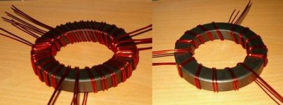
i had some problems to cover the whole core with only 4 turns , after couple of tries i finally decided to do this that way , i have divided the core into 3 sectors as Eva said making 4.5 turns within each sector -heres the pic , on the right side one primary and on the left side bought primaries , looks kind of messy isnt it ?😀Originally posted by Eva
Another option is to divide the core in two or three equal sectors and wind two or three independent primaries [one for each sector] connecting them in paralell externally
Attachments
A couple of things - I made the point about the mosfets because they are easy to heat sink - I would never release a design with 1.5W on a bare TO-220 package, as it would be hotter than blazes. This same dissipation spread across several mosfets is quite ok. It's a good idea to be careful, though, as the automotive environment is about the worst in the commercial world for temperature extremes. Assume a 60C ambient when thinking about heat sinks. It's a good idea to keep the worst case lead temperature to about 100C or less. The devices will like it, and higher temperature risk browning the circuit board if applied for too long. Anyway, my point was that 1.5W loss in the mosfets is managable, but 1.5W in a short length of copper wire is very hot - one should budget a lot less winding dissipation than that, especially considering the lousy operating environment. Even if the insulation doesn't flake off the wire, it will heat up the core, and the core saturation flux density will go down by at least 1000 Gauss if the core is heated up to 100C - probably more if it's an off-brand ferrite. You want to have as much flux margin as possible, as differences in output rectifiers voltage drop, primary layout, or switch voltage drop can cause the transformer flux to walk to one side.
I beg to differ about the current spikes. During normal operation, the the magnitude of any current spikes will be determined by the output load and the output capacitance, and power supply dead time. There will be some capacitor discharge during the dead time. This will cause some spiking when the output switches come up again. It is not a good idea to blithely assume that there will be no current spikes, especially with a high power load like 200 watts or so. You need to look at the dead time of the chip for its particular operating frequency and timing component values. You can estimate the voltage dip during dead time by assuming the load is a current sink (not a bad assumption if the dip is small or the output voltage is high), and use the equation: delta V = (i*delta t)/C, where I is the load in amperes (coulombs/second), delta V is the voltage dip in volts, delta t is the dead time in seconds, and C is the filter capacitance in Farads. Model the leakage inductance as an inductor in series with the primary, and the dip voltage as multiplied by the turns ratio. You have an LC circuit with the leakage inductance and the output filter capacitance, with a step input. Filter capacitance can be increased to reduce this spike, but the kicker is that there will be tremendous current spikes when the unit powers up, as the discharged output capacitors represent a nice short circuit. Since most users are using step-up transformers the current into the capacitors is multiplied to the primary by the turns ratio. There is no way to avoid this using a simple inverter circuit without output inductor. Soft start will not help, as there is no intervening impedance to limit the capacitor charging current, even with short duty cycle. The primary switches may or may not survive this abuse. Monitoring the startup current with a current probe will give you a result that will make your hair stand up on end, and the current probe will probably saturate. MOSFETs are tough, so there may be a good chance that the switches will survive this abuse repeatedly. The chances are less certain as the power capability goes up, as al the circuit impedances must go down. Picking out a weak MOSFET this way may cause a lot of collateral damage.
This is not to say that failure is ceratian with this approach, but it is prudent to do a little investigating beforehand to weed out any problem areas. I am used to designing power supplies for million-piece builds - a failure rate of 1% means 10,000 dead power supplies and an angry customer. You get the failure rate down by looking for trouble areas before you ship the product and making the supply bullet proof. For those who want to try it, a more bullet-proof design is to use an LC output filter and add the components around the switcher chip necessary for soft start.
To give people an idea of what to expect in terms of leakage inductance, I'll try and see if I can find one of my nice epoxy-coated cores and wind up a transformer for about 200W, with an output voltage of +/-40V peak. I have the equipment at work to completely characterize the transformer. It'll take a while, as I just moved not too long ago, and a don't have a really clear idea where to find things...
Let´s assume a single 12V to 48V converter [4:1 turn ratio] running at 50Khz [100Khz oscillator] with 10.000uF output capacitance, 60A/15A input/output currents, 80% duty cycle and 480nH leakage inductance as seen from the secondary with shorted primary [30nH leakage indutcance as seen from the primary with shorted secondary]
Let's calculate the voltage change across a 10.000uF capacitor loaded with 15A during 2us [dead time period] :
v = i * t / C = 15 * 2e-6 / .010 = 3 mV
THE INDUCTIVE COMPONENT :
Then, let's calculate how much time takes a 480nH inductor with 3mV applied to reach 60A current :
i = v * t / L
t = i * L / v = 60 * 480e-9 / .003 = 9.6ms
This demonstrates that the resistive voltage drop on all components is what is driving the leakage inductance to slowly reach the required current level on each pulse and that capacitive voltage fluctuations across the output capacitor are negligible compared to overall resistive voltage drops
THE RESISTIVE COMPONENT :
Also, if we assume .003 ohm total resistance as seen from the input with shorted output this means .048 ohms as seen from the output
So 3mV applied to .048 ohms cause a huge current spike of :
i = v/R = .003/.048 = 62.5mA
This also demonstrates that the resistive component dominates on the circuit and doesn't allow for any current spike to happen
Actually, these converters allways provide lower output than expected since this voltage difference is what drives the leakage inductance to reach the required current
Finally, the peak current reached at startup is proportional to the duty cycle rise slope, so slowing the start-up to a couple of seconds ensures low currents. Remember that during the first cycles the duty cycle is so small that MOSFETs are not allowed to fully turn-on and operate on their linear region thus naturally limiting peak current
one more thing
can i cover the primary winding with some kind of duct tape so it will be easier to wind the secondary ?
its gotta be some kind of special tape right?
thanks
can i cover the primary winding with some kind of duct tape so it will be easier to wind the secondary ?
its gotta be some kind of special tape right?
thanks
National Semi E-Conference -- Magnetics
all you would-be SMPS designers might be interested in National Semiconductors E-Seminar discusssing "magnetics" -- it can be found at:
http://www.national.com/onlineseminar/2004/magnetics/magnetics.html
of course, you have to register.
all you would-be SMPS designers might be interested in National Semiconductors E-Seminar discusssing "magnetics" -- it can be found at:
http://www.national.com/onlineseminar/2004/magnetics/magnetics.html
of course, you have to register.
I am no super pro on this, and I assume you're going to use it for a car supply, I think the Drain to Source voltage is too low. in a 13.8 V car, you're going to see 27.6 volts from drain to source, plus a minor turn on overshoot. I personally prefer the Fairchild UltraFETs, (check these out) they tend to have a lower gate charge and capacitance, and the fall time is very quick, turn off delay+fall time is only 45nS compared to 88nS with those ONsemi devices. If you really get into SMPS, and I'm sure some others on the site can tell you as well, getting the MOSFETs to turn off quickly is important. All I know is that I have used both these fairchilds and these ONsemis in the same power supply design, and the Fairchilds gave much better waveforms.
As for the toroid, if you really want 1000W RMS, two toroids will suit you best, use one for each primary. You could probably get away with 6 mosfets for each primary, though 8 would be better. Also, if you're doing an A/B with a bias of over 60%, you'll want to heatsink the mosfets separately from the amp, most car amps just use the same big heatsink(case) for all of them, but the heat produced from a highly biased A/B won't allow your MOSFETs to dissipate heat, especially in a car. You may even want to make the power supply its own separate module.
As for the toroid, if you really want 1000W RMS, two toroids will suit you best, use one for each primary. You could probably get away with 6 mosfets for each primary, though 8 would be better. Also, if you're doing an A/B with a bias of over 60%, you'll want to heatsink the mosfets separately from the amp, most car amps just use the same big heatsink(case) for all of them, but the heat produced from a highly biased A/B won't allow your MOSFETs to dissipate heat, especially in a car. You may even want to make the power supply its own separate module.
- Status
- Not open for further replies.
- Home
- General Interest
- Car Audio
- toroid for car amp smps