Eva,
Don't take my comments wrongly. I just amazed you have such a skill in smps. It takes me years to learn it. I'm not sexist or racial or have problem with gender. Infact, I think if female do electronics, they should present better output because male tends tobe not too patient and often overlooked something. In audio electronics, details are important.
Sometime ago, there is a thread here asking wheter there is any female in Diyaudio forums. Eversince that thread, I see more female posting here. Nothing is wrong with that. Why dont you post your pic for avatar?
eva,
all the while i was thinking that the letters in your handle represent the first letter of your names, i feel relieved that that issue is settled, not that it mattered really....
anyway what's between your ears matters more than what's between your legs.....pardon the expression....
i really admire the way your explain things....knowledge is not acquired only in school....most of what i learned, i got out of school...and is not much as i realized reading thru these forums...
stay hot....and post on!!!!
tony
Hmmm... the edit button seems to be missing. If my math is correct, I can use 2 of these 20 ga. wires for my secondaries at about 1.5 watts. (assuming about 1 meter secondaries, I measured) Sound good?
These diodes are great, they have pretty fast reverse recovery for their voltage rating, but they are expensive and you don't need such high a voltage blocking capability, cheap 200V diodoes from Motorola are equally fast and will do the job for less money and up to +-80V unregulated outputs
I've thought sometimes about buying hyperfast diodes from fairchild to use them in high voltage PFC or buck experiments where 450V blocking and very fast reverse recovery are required, but I'm allways short on funds so I end buying cheap Motorola stuff
It hurts less to blow cheap devices...
For secondary magnet wire selection take into account that more air-exposed wire area allows for more dissipation with same temperature increase. If you had 1.5W for each primary with 6x 0.2m=1.2m total lenght of wire, you may allow 3W for each 2m secondary. If primaries are somewhat internal and secondaries are somewhat external you may also allow even higher dissipation on secondaries
Remember to wind it as thight as possible to reduce secondary wire length and leakage inductance
If you are planning to test the amplifier with 2 ohms at full power [ie: bridged], I recommed increasing wire cross section of both primaries and secondaries since my initial calculation of 35Arms per primary was for 4 ohm per channel operation [winding and board-mounting the transformer with more magnet wire will be somewhat harder]
Actually, that's about right, because each of my two channels pulls about 230 watts in 2 ohm. I realize that I'll have to put more than 460 watts in to get 460 watts out, so I decided to stick with the six-.8mm primaries though you mentioned that I could use less. I really have only planned on using 37V rails on my circuit, but I am shooting for 40 because you always seem to get less voltage under real world operation. Does that sound reasonable?
Also, I could send you some of these diodes if you have a special project in mind, I think you deserve it, you're one of the few that actually stick with people until they get it right.
Also, I could send you some of these diodes if you have a special project in mind, I think you deserve it, you're one of the few that actually stick with people until they get it right.
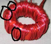
Ok, does this look too sloppy to work right? I used two wires for eah secondary.
An externally hosted image should be here but it was not working when we last tested it.
You may try to wind the secondaries turning two or three times around the entire core, instead of just one time, to increase wire tilting. It will also require more wire lenght but leakage inductance won't increase
Another option is to divide the core in two or three equal sectors and wind two or three independent primaries [one for each sector] connecting them in paralell externally
Wire crossovers are ok as long as you coat the core with varnish, epoxy or something consistent but flexible that allows some dilatation but avoids wire vibration and/or displacement. Otherwise, once the amplifier is installed in the car and exposed to vibrations, you will get random shorts between turns/windings in the long term [this happens also in some brands of commercial amplifiers]
Also, I recommend glueing heavy components [like big capacitors] to the PCB since vibrations cause stress to the leads and this produces fractures or bad solder joints in the long term
as far as the crossing, does it matter if they are the same winding? Basically, the ones circled in the pic above are parallel windings on the same secondary. I will try to straighten them out, but just wanted to know.
Eva, you are just a miracle!!!  Respect from Russia!!
I'm repairer too, and completely agree with your opinion about caraudio. Sometimes i feel that all of the caraudio amps(<$300), actually made by single company, which own different trade marks. Maybe caraudio buyers usually rich and deaf? IMHO, the main stream industry left caraudio sector forever. 😉
Respect from Russia!!I'm repairer too, and completely agree with your opinion about caraudio. Sometimes i feel that all of the caraudio amps(<$300), actually made by single company, which own different trade marks. Maybe caraudio buyers usually rich and deaf? IMHO, the main stream industry left caraudio sector forever. 😉
I think there are a dozen or so of car-audio manufacturers, in China and nearhoods, that sell finished amplifiers in custom cases to all car-audio brands
These amplifiers are nothing but small variants of the same circuit using the same components. You can easily find $200 and $400 or even $500 and $1.000 amplifiers having the same schematic and components
There are very little manufacturers buying custom electronics designed for them in exclusive and almost no manufacturer develops his own amplifiers. They know nothing about amplifiers except how to sell them
Your thoughts are good. If turn number 3 of one winding strand shorts to its counterpart, then the result would not be a shorted turn and catastrophic failure. But as Eva mentioned, if the enamel wears off at the contact point, it can cause a little variation in the transformer behavior. A cross also pulls the winding away from the core a little, slightly altering the coupling, and usually with each cross, another cross must bring the winding back into proper position. It would be worse with more than one layer. The crossed wires take up much more space.
A trick I use before I wind toroids is to start with about a 1 to 2 foot length of the winding and then bend the wire back in half and spiral it back down along the 1st length. Keep going back an forth so that you end up with a stick of spiraled wire. Each spiral twists in the direction opposite to the one below it. You now have a wire stick to feed around and around the toroid unraveling it little by little as you add turns. This method is most helpful for winding large toroids with many turns--mostly irrelevant for SMPS power supplies for audio.🙂
A trick I use before I wind toroids is to start with about a 1 to 2 foot length of the winding and then bend the wire back in half and spiral it back down along the 1st length. Keep going back an forth so that you end up with a stick of spiraled wire. Each spiral twists in the direction opposite to the one below it. You now have a wire stick to feed around and around the toroid unraveling it little by little as you add turns. This method is most helpful for winding large toroids with many turns--mostly irrelevant for SMPS power supplies for audio.🙂
not sure. I'ts some sort of solid, enameled magnet wire that is sold as and can be used as either a spool of wire or a 1.6mH air-core inductor.
probably. anything will work as long as it's thin and insulative. I've even seen some toroids with woven fabric on the primary in addition to the enamel. Enamel probably is polyurethane, I'm just not worried enough about it to notice when I select my magnet wire.
- Status
- Not open for further replies.
- Home
- General Interest
- Car Audio
- toroid for car amp smps