i'm using 5 wires of 1mm diameter for the primary , thats too much i think 🙄 . u can use 6 of 0.4 mm wires for the primery to get >300W o power . for that big amp of yours i think u should use 6 of 0.8mm or 1mm .
lumanauw said:I've got a big project ahead. Class AB power amp for driving car subwoofer. The audio amp voltage is +/-75V. But I wanted this car amp able to drive 1 ohm load (for bridged parrareled car subwoofer).
I've got 1cm2 Ae ferrite core. The pushpull smps will be working 30khz (60khz clock).
Due to skin effect theory, I have to use small size wires in parrarel.
1. What is the good wire size? I think about 0.8mm wire magnet in parrarel.
2. How many wires will be needed for primary? What is the calculation?
3. How many wires will be needed for secondary?
you can determine the primary and secondary windings using the spreadsheet in at: http://www.tech-diy.com/smps_xfmr.xls I spent a couple hours writing the spreadsheet using the design equations from Linear Tech's website.
the wire size will depend upon the peak and average currents you expect to engage -- this then determines the SIZE of the core that you need -- the core MATERIAL has to be chosen such that the core doesn't saturate.
Ok, first thing first. If the amp is +/-75V, and wanted to be able to drive 1ohm speaker, what is the current number for smps design. If I take simply 75V/1ohm=75A. Is this too astronomical? If it is too big, what is the current rating of the smps should be?
lumanauw said:Ok, first thing first. If the amp is +/-75V, and wanted to be able to drive 1ohm speaker, what is the current number for smps design. If I take simply 75V/1ohm=75A. Is this too astronomical? If it is too big, what is the current rating of the smps should be?
here's where a textbook would come in handy -- the peak current that flows through the primary of the SMPS transformer is significantly greater than current demanded by the load itself -- depending upon the topology.
i think we are in the realm of #8 AWG , but haven't actually chedked.
lumanauw:
u are making an amp with 75V lines to drive an 1ohm speaker
P=(Vcc*Vcc)/(2*R)
P- power for the load
Vcc- rail voltage
R- load resistanse (impedance 😀 )
so u are making :
(75*75)/(2*1)= 2812.5W AMPLIFIER !!!😀
are u sure thats what u wanna do ?
oh wait u want to bridge that amp 🙄
in bridge mode the rail voltage will be 75*2=150V 😱 😱
so the power output into 2 ohm bridged load will be 5625W 😀
for that power the battery will need to supply approx 500A to your primary coils
@sss:
Your solution sounds OK.
So you are using the feedback loop to reduce the duty cycle, right?
@lumanauw:
You are going to an excessive project, in fact.
Please note, if your amp can deliver max. 5kW... 6kW 😀 ....
OK, the average power will be much less, normal music programm has a crest factor around 10. So if the drums drive your amp close to clipping (5kW...6kW), the average power is around 500W...600W.
So your power supply must be able to handle 6kW for short times, but the thermal construction does not need to be designed for continuous 6kW.
Wire size:
A difficult thing to optimize. If you have a torroid transformer with single or dual layer winding, then the approach with the skin effect is sufficient. At 30kHz you could go for paralleled wires strands around 0.6mm to 0.8mm.
If your winding is not only some turns in single or dual layer, but the winding area looks more like a block of "thousand of wires"..., then the paralleled strand must be thinner.
The skin effect describes the self induced current displacement of a single wire. If you bulk together a lot of wires, then the distribution of the current density in the wire will also be influenced by the field of the surrounding wires. This is known as the proximity effect.
So depending on the shape of your winding area, you might easliy end up at paralleled strands around 0.2mm at 30kHz.
(And you are still lucky, as you do not have a gapped core.
In a design with a gapped core you would also have to take care about the leakage field around the gap. This would induce eddy currents and could easily force you to 0.1mm stranded wires...!)
Good luck
Markus
Someone has done it
Not dreaming, someone has done it. Look at http://www.maaudio.com/productcatalog.cfm?class=233
HK4000D.
Or http://www.clifdesigns.com/productcatalog.cfm?class=521 CDX-20A. They are the same thing inside. These are one of the most powerfull car amp I've encountered.
It sizes (W x H x D) 12.4” x 2.71” x 25.86”. Inside, there is 2 amps working in bridge mono. The rails are +/-75V, having 2 toroids inside, not so big, with no so much wire. Can handle 2 ohm load (means 1 ohm for each amp).
The amp is said ClassX, I dont know what classX is, but it seem a each amp is classD, so 2 of them will make full bridge configuration at output.
The real beast is this. 8110Watt at 4ohm. 😱 http://www.jbl.com/car/products/product_detail.aspx?prod=A6000GTI&ser=GTI&cat=AMP JBL-CROWN 6000. The toroid is bigger than your average coffee donuts. The amp is design by CROWN (pro-amp manufacturer) with BCA technology. Anyone knows what is BCA? What is the difference with full bridge classD?
These are not-normal car amplifier. Usually used for competition. It will certainly needs big alternator and extra battery, if you dont want to ruin your car's electrical system.
This is the calculations I got for +/-75V at 75A output smps. The calculation based from Mag-Inc Guidelines.
If I have a core with 1.44cm2 Ae, I will have 4 turns primary with 303wires of 0.8mm. I will have to put 30 turns of 37wires of 0.8mm for secondary.
No car amp in the market do this, even those examples above. Their primary and secondary number of wire are so little. Max parrarel wire I've seen is 10 in parrarel, not more. What is really the calculation for wire needed in car smps? Is it differs from handbooks? Or is it the design-current is only 10% like ChocoHolic suggested?
I had the oppertunity to talk to one of the JBL Reps at last years DB Drag World finals in nashvill, TN.
That Crown amp is STOUT.
A) Just the Remote turnon is an 8ga input.
B) When asked what the lowest impeedance it would play the rep replied "A DEAD short". He Said the engineers wrapped two wires to a wrench and it played.
C) Don't even think of useing it unless you got a spare battery and I think 5 farads of capasitance on the input.
Yea it's a Bad amp with a 6K$ price tag
Re: Someone has done it
but i think thats stupid to make an amp that powerfull . i rather enjoy muic then making allot of noise - thats what those amps are supposed to do .
non of these amps u showed can actually do that , maybe for a microsecund.
who said u are dreaming ? 😀lumanauw said:Not dreaming, someone has done it. Look at ....
but i think thats stupid to make an amp that powerfull . i rather enjoy muic then making allot of noise - thats what those amps are supposed to do .
also needed - a deaf driver 😀lumanauw said:These are not-normal car amplifier. Usually used for competition. It will certainly needs big alternator and extra battery, if you dont want to ruin your car's electrical system.
303 wire if u want the core to handle 500A primerylumanauw said:This is the calculations I got for +/-75V at 75A output smps. The calculation based from Mag-Inc Guidelines.
If I have a core with 1.44cm2 Ae, I will have 4 turns primary with 303wires of 0.8mm. I will have to put 30 turns of 37wires of 0.8mm for secondary.
non of these amps u showed can actually do that , maybe for a microsecund.
Hahaha...
A deaf driver? Yes, plus one crazy mind.
But if you are in SPL contest you will find that kind of person existed, and alot of them.
I just take it as a technical challange. Imagine you built 8000W power amp and you can tied together the outputs without breaking the amp, I would call that technical excellence.
Please note:
The crest factor of 10 does not mean that the current rating of the transformer has to be designed to 10% !!!
If we assume that the full power has to be delivered with "duty cycle" of 10%, then the transformers current rating is going down only by the root of 10.
(Well, your wire design seems to be rugged anyway 😀)
Take care for your MosFets...
Bye
Markus
How to peel magnet wire?
I really need help. Making car smps with toroidal core sure needs magnet wire. The size I'm using is 0.8mm
How can I peel the magnet wire (solderable)? Looking at the factory made, they are very clean, looks like dipped into some chemical.
Currently I use manual stripping, using a cutter.
Some said to burn them, it dont work. Using sand paper, it takes longer than peeling with cutter.
In the net there are factories who sells stripping/peeling device, but quite expensive.
Does anyone knows how the car amplifier factory peel their magnet wire? If it is with dipping into somekind of chemical, what is the name of the chemical?
simply scratching it with a knife or cutter works for me , if u got thick windings with many wires than its really starts to annoy 🙂
Ya, those works fine if we only peel 3 or 4 wire.
This becomes a problem if we have to peel 50 or 100 wire ends.
Anyone knows how factory do it?
This becomes a problem if we have to peel 50 or 100 wire ends.
Anyone knows how factory do it?
They get that with a solder pot. You can get that by tinning the
crap out of the wire end.
By the way, a solder pot costs about $30
crap out of the wire end.
By the way, a solder pot costs about $30
I use a 150W soldering iron and *lots* of solder flux [it gets dirty quickly]. My record is 10 wires of 1mm diameter at the same time
I think that transformer manufacturers remove enamel by leaving the wire inmerse in melt solder flux [maybe at 250ºC] for several seconds
I think that transformer manufacturers remove enamel by leaving the wire inmerse in melt solder flux [maybe at 250ºC] for several seconds
Hi, Mr.Pass,
Sorry, my English is bad. What is a solder pot?They get that with a solder pot. You can get that by tinning the crap out of the wire end.
My english is not better than yours but I think a 'solder pot' is a metal can with a built-in heater and filled with hot melt solder flux. [In my previous post I was just trying to say 'solder pot' but I didn't remember the exact words]
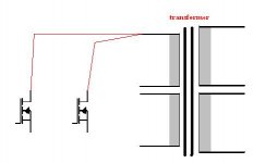
i was thinking of a different way connecting the primary coil of the transformer to the fets :
lets say the primary winding consists of 4 single wires and i'm gonna use 2 pairs of fets per primary .What if i will connect 2 wires of the winding to one fet and the other 2 wires to the other fet without connecting the whole wires of the primary all together is it a bad idea ?
ps
welcome back Eva 😀
lets say the primary winding consists of 4 single wires and i'm gonna use 2 pairs of fets per primary .What if i will connect 2 wires of the winding to one fet and the other 2 wires to the other fet without connecting the whole wires of the primary all together
is it a bad idea ?ps
welcome back Eva 😀
Attachments
- Status
- Not open for further replies.
- Home
- General Interest
- Car Audio
- toroid for car amp smps