Ahh, premodded, i have the mod and i still am looking at attenuating the tweeter ~6dB. sounds better all around that way.
at the price he charges, i think i may just go with Ed Frias' crossovers, maybe i learn something from what he does, or so i hope.
at the price he charges, i think i may just go with Ed Frias' crossovers, maybe i learn something from what he does, or so i hope.
Ive just ordered some resistors that will allow me to attenuate the tweeter on my speakers by 2-4db, will check back with my findings when they arrive!
Attenuating the tweeters on my speakers by 3db seems to have done the trick. Very happy with my little university bedroom set up now.
I'm not an audiophile, but have stumbled upon the TP20 and have been impressed by all I've read. I have one, hopefully simple, question:
I have a pair of Goodmans Acromat 400 speakers that I've had for 30 years. I love the sound, but I remember very little about their specs. I think they are rated 75W @8ohms. My question is this - can the TP20 successfully drive speakers like this. I'm not looking for a big sound, just a quality one. Thanks.
I have a pair of Goodmans Acromat 400 speakers that I've had for 30 years. I love the sound, but I remember very little about their specs. I think they are rated 75W @8ohms. My question is this - can the TP20 successfully drive speakers like this. I'm not looking for a big sound, just a quality one. Thanks.
It drives my 8Ohm speakers easy enough, but i am using them for near field listening mostly.
The 90dB certainly help, but i can easily fill a decent sized room with sound too. I use the TP10 MkIII btw.
And if you love your bass, pick up a modified one or modify it yourself, if you read the thread, you know how easy that would be.
Hope this helps.
Daniel
The 90dB certainly help, but i can easily fill a decent sized room with sound too. I use the TP10 MkIII btw.
And if you love your bass, pick up a modified one or modify it yourself, if you read the thread, you know how easy that would be.
Hope this helps.
Daniel
I was thinking of getting a regulated 13.8v supply for my TP20 but have just noticed the two D0 diodes required for operation of the tripath chip above 13.5v are missing, would it recommended to install these before doing this?
minusthetom said:I was thinking of getting a regulated 13.8v supply for my TP20 but have just noticed the two D0 diodes required for operation of the tripath chip above 13.5v are missing, would it recommended to install these before doing this?
Hi, minusthetom,
I have a modded TP20 that I run off of a homebrew SLA supply, when the battery is fully charged it it delivers about 13.5 volts and have had no trouble with this.
I am not familiar with the 'two diodes' that you mention, this to me sounds more like half wave rectification rather than an over voltage protection? Could be wrong though
😕
I guess an option would be to change the regulator in the supply to a lower voltage....
cheers.. Steve
Sorry I wasn't all too clear with my post!
The output stage for the tp20 is identical to that found on the ta2020 data sheet with the exception of a couple of capacitor values and the omission of 4 Schottky Barrier diodes (2 per channel) which connect to Vd. Tripath state that the diodes are required where VDD exceeds 13.5 volts to "minimize overshoots of the outputs with respect to VDD during switching transitions".
🙂
minusthetom said:Sorry I wasn't all too clear with my post!
The output stage for the tp20 is identical to that found on the ta2020 data sheet with the exception of a couple of capacitor values and the omission of 4 Schottky Barrier diodes (2 per channel) which connect to Vd. Tripath state that the diodes are required where VDD exceeds 13.5 volts to "minimize overshoots of the outputs with respect to VDD during switching transitions".
🙂
I downloaded a copy of the Tripath TA2020 datasheet, the question you ask about the Schottky diodes might be better answered by Arjen.
I note the data sheet shows that the typical input voltage required is 13.5 with a maximum of 14.6, which again goes to prove that you have nothing to worry about with your proposed regulated power supply.
I have been very happy with my TP20, I am now considering trying an Argen Helder Mk III TA2020 in a slightly larger enclosure as modding the TP20 is a bit of a squeeze.
cheers.. Steve
I've a TP 10 Mk3. The bass is pretty weak. I want to mod but i don't know which is the input capacitor and the buffer cap. Anyone can help me identify them?
I've got a TP 10 MK3. the bass is weak. I want to mod but I do know know where to solder the caps for the 12v line and which is the input cap. Can anyone help me identify them?
I've got a TP 10 MK3. the bass is weak. I want to mod but I do know know where to solder the caps for the 12v line and which is the input cap. Can anyone help me identify them?
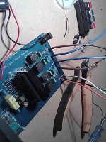
Hi Kakaxi, add the capacitor(s) across the 12v input, mine is + to the switch and - to the DC input socket (TP20) I'm sure that you could easily identify the + & - supply onto the board, choose somewhere where you can easily solder a wires for the capacitors.
I'm sure that you will be happy with the result
cheers.. Steve
Attachments
I have four 4400uF 25V cap´s that i wanna put in my Topping tp-10 Mk3.
why the voltage in cap´s have to be 25V? even the input voltage is only 12V?
Do I have to loverdown the cap´s Voltage somehow?
Is it ok if I only put 3 Cap´s if i´dont have enough space for four cap?
why the voltage in cap´s have to be 25V? even the input voltage is only 12V?
Do I have to loverdown the cap´s Voltage somehow?
Is it ok if I only put 3 Cap´s if i´dont have enough space for four cap?
I have Arjen's modded t-20. I'm quite happy with it. I don't hear any issue with treble brightness fwiw, but that could be due to a lot of factors.
He has talked about doing a pre-built amp of his own and I'm looking forward to hearing about and listening to that.
He has talked about doing a pre-built amp of his own and I'm looking forward to hearing about and listening to that.
I have four 4400uF 25V cap´s that i wanna put in my Topping tp-10 Mk3.
why the voltage in cap´s have to be 25V? even the input voltage is only 12V?
Do I have to loverdown the cap´s Voltage somehow?
Is it ok if I only put 3 Cap´s if i´dont have enough space for four cap?
The voltage rating of the capacitor should be above that of what it is being used at, the written rating on the capacitor is what it's dielectric is rated at.
So a 25V rated cap is perfect for 12V.
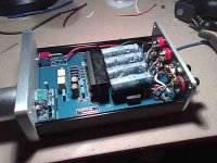
I would think that two of your 4400uF cap's would be more than adequate for your TP10. 8800uF tank cap is good 😉
The voltage rating of the capacitor should be above that of what it is being used at, the written rating on the capacitor is what it's dielectric is rated at.
So a 25V rated cap is perfect for 12V.
I would think that two of your 4400uF cap's would be more than adequate for your TP10. 8800uF tank cap is good 😉
Thanks! 🙂 two it´s gonna be. easy to fit.
I also going to change the two 220uF caps that are original inside, for 1000uF caps. Is that also Ok or is´t a waste of time?
Thanks! 🙂 two it´s gonna be. easy to fit.
I also going to change the two 220uF caps that are original inside, for 1000uF caps. Is that also Ok or is´t a waste of time?
The capacitors that I think you are referring to are the two 220uF input caps, I would strongly advise you not to increase the size of these as you will probably damage the 2020 chip 😱
You might consider installing better quality film caps in their place of the same value (220uF) Mundorf's, Auricaps or something similar.
Last edited:
Newbee with bad english needs help
Hello
I´m fresh infected with the T-virus😀
I have a question about the TP10 Mark 3:
The C17 and C18 are polar caps 3,3 µF can i change them with non polar 3,3µf???
Or what should i do???
The other amps with the 2024 have non polar caps why this not?
Correct me if i´m wrong!
Greetings from cold Germany
Hi Kakaxi, add the capacitor(s) across the 12v input, mine is + to the switch and - to the DC input socket (TP20) I'm sure that you could easily identify the + & - supply onto the board, choose somewhere where you can easily solder a wires for the capacitors.
I'm sure that you will be happy with the result
cheers.. Steve
I have two 2024 topping amps currently vertical bi-amping.
I would also like to try this mod.
I am not very literate with the technical side. does the capacitor have a + and - to it?
how about a simple sketch for this much talked about upgrade Please,
- Status
- Not open for further replies.
- Home
- Amplifiers
- Class D
- Topping TP10 Mk3 and Topping TP20 impressons?