yeah, i like that... sir tony can you give me the right computation of toroidal 70 volts and 12 volts? in the EI Core transformer here is my computation.
http://www.diyaudio.com/forums/powe...ion-ei-core-transformer-philippines-base.html
http://www.diyaudio.com/forums/powe...ion-ei-core-transformer-philippines-base.html
^you need to give me the dimensions of your torroid core, inside diameter, outside diameter, height......
torroid cores operate with higher T's.....more than EI's....
torroid cores operate with higher T's.....more than EI's....
[b]blue, blue, my traffos are in blue:[/b]

8k a-a primaries to 4/8/16ohm secondaries:

with power traffo:

4k a-a primaries to 4/8/16ohm secondaries:

with power traffo:

two sets of irons for two amplifiers:

8k a-a primaries to 4/8/16ohm secondaries:
with power traffo:
4k a-a primaries to 4/8/16ohm secondaries:
with power traffo:
two sets of irons for two amplifiers:
lovely - very well done - those end bells look fantastic. was wondering today how hard it would be to press them from sheet steel if you had a mandrel made ect and used a 12T press. definately going to have a go at this - i found the winding tool on fleabay also so I will order one from hong kong and give it a try. we can (locally here in AU) get the E I and bobbins / copper wire no problems.
Grega,
50/60 hz Laminated Transformers use Silicon steel instead of ordinary steel to reduce core losses.
Electrical steel - Wikipedia, the free encyclopedia
50/60 hz Laminated Transformers use Silicon steel instead of ordinary steel to reduce core losses.
Electrical steel - Wikipedia, the free encyclopedia
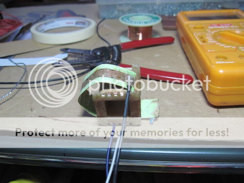
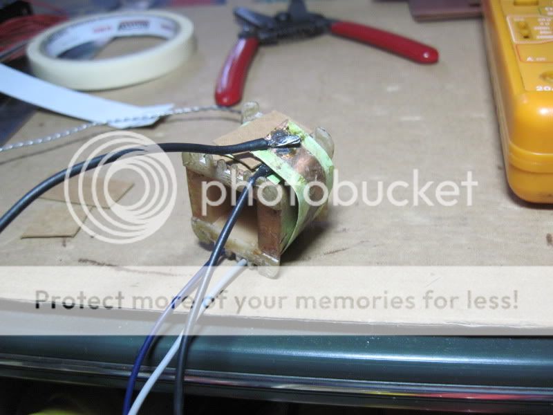
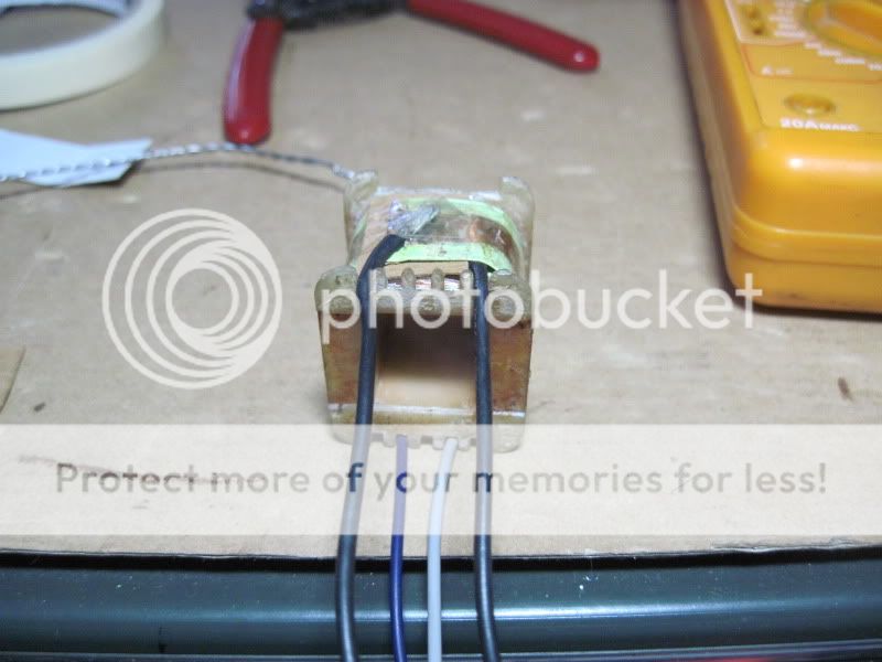
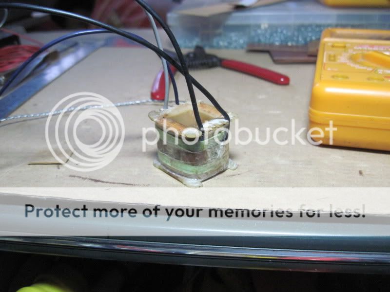
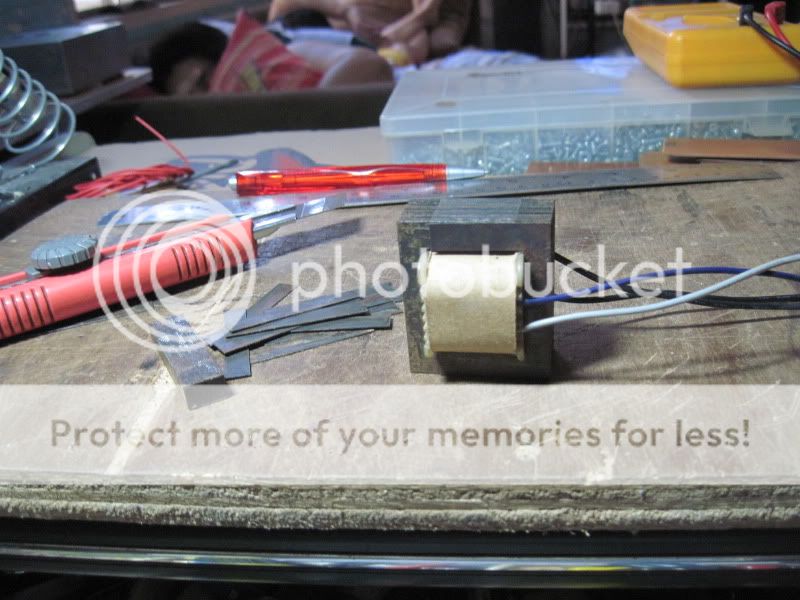
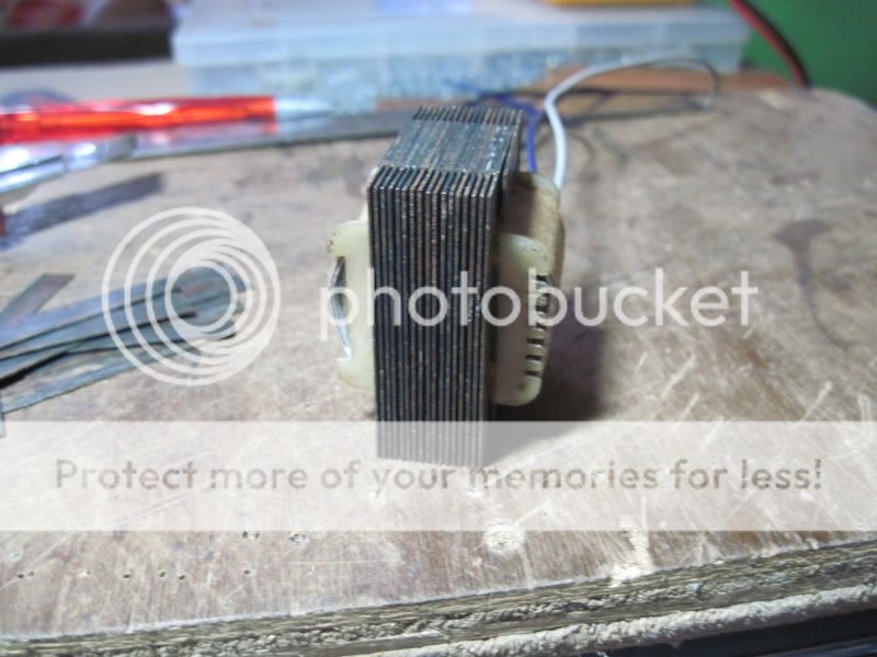
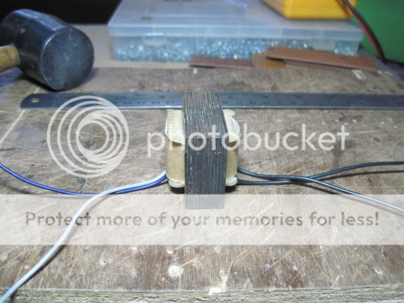
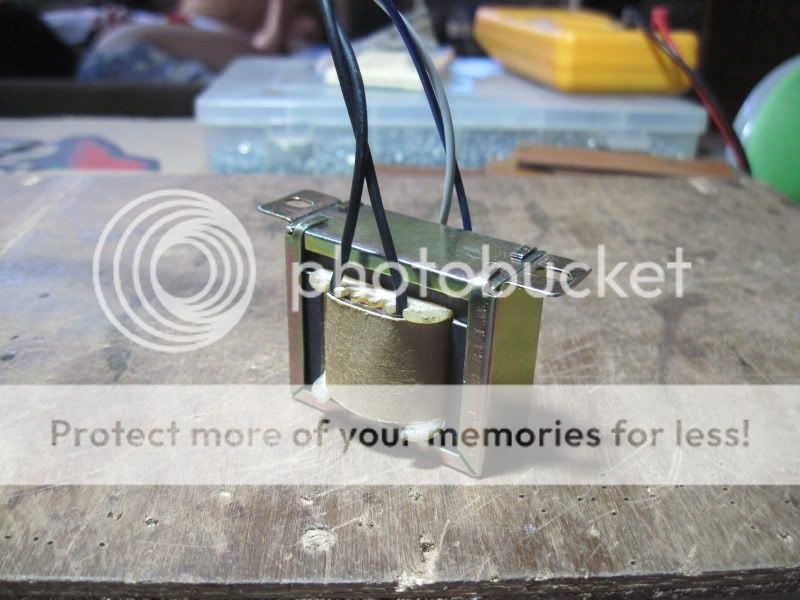
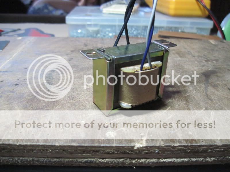
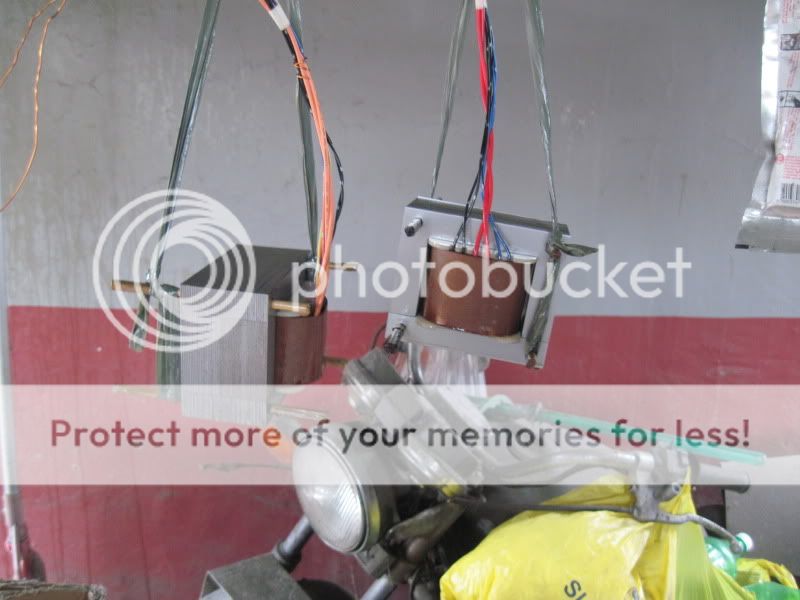
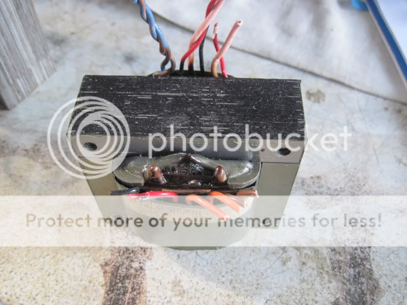
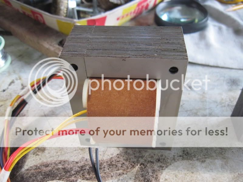
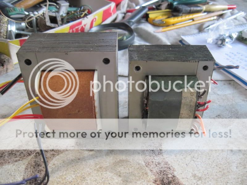
traffo for a 12AX7 tube preamp.....
2 traffos, one for plate B+, 280volts at 50mA, the other one for filament supply, 12-0-12volts at 0.8A
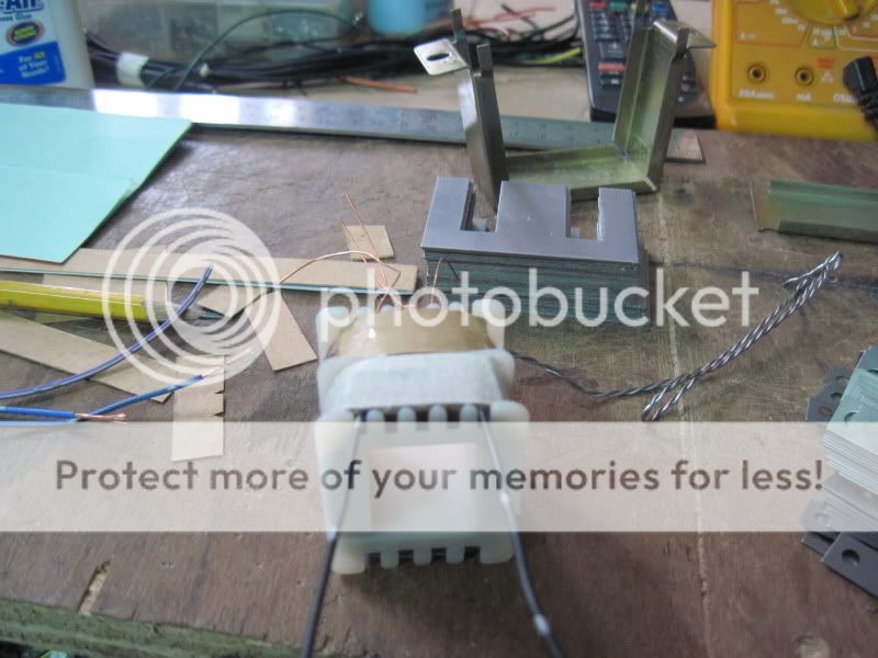
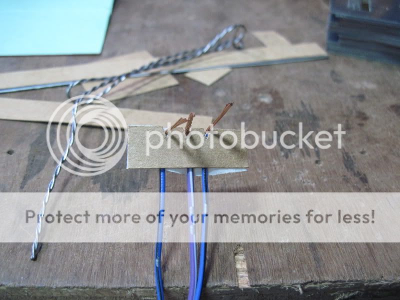
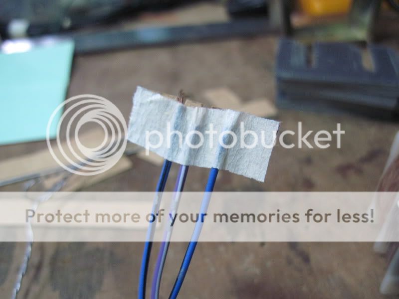
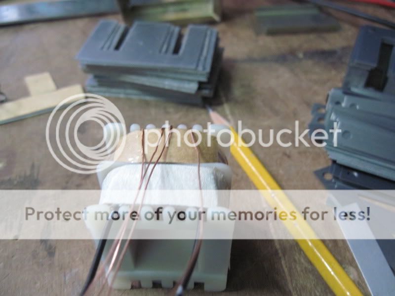
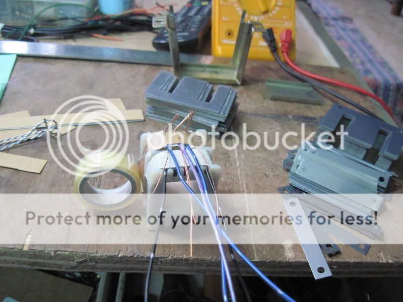
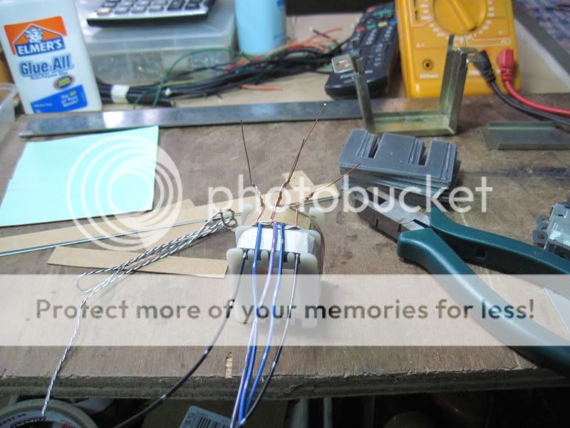
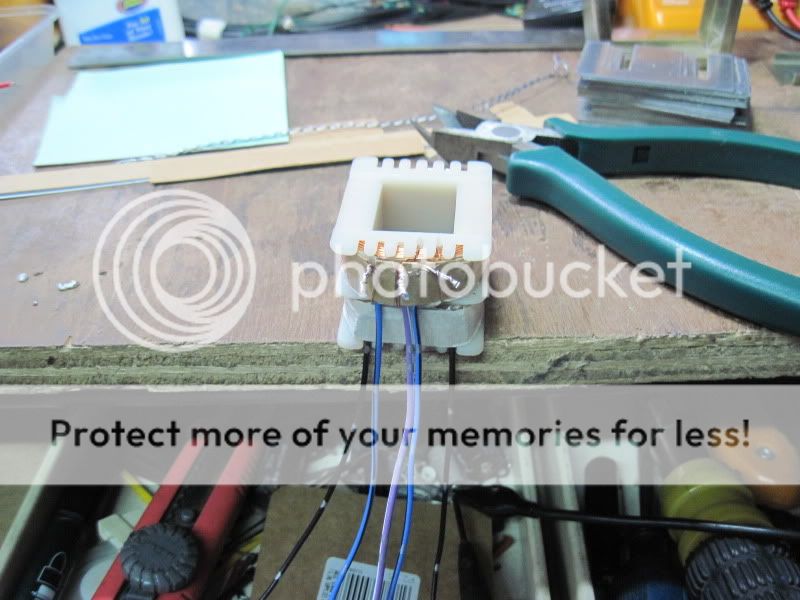
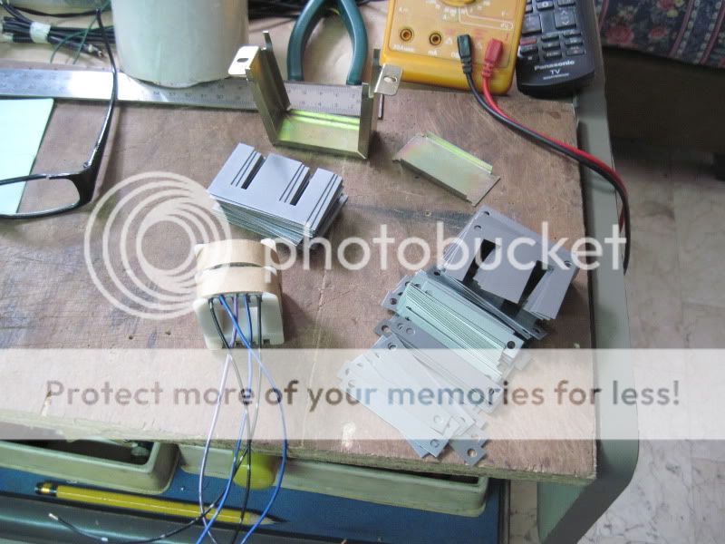
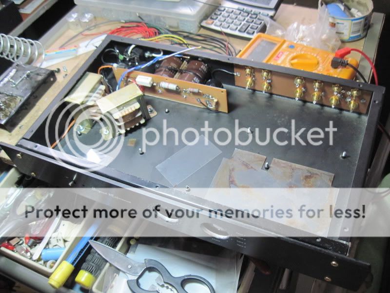
installed inside the preamp chassis:
2 traffos, one for plate B+, 280volts at 50mA, the other one for filament supply, 12-0-12volts at 0.8A
installed inside the preamp chassis:
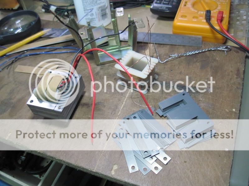
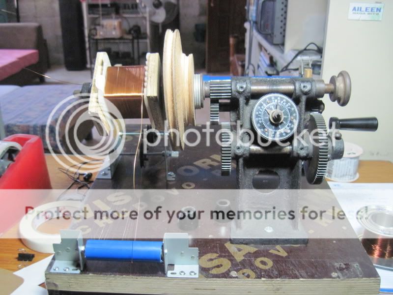
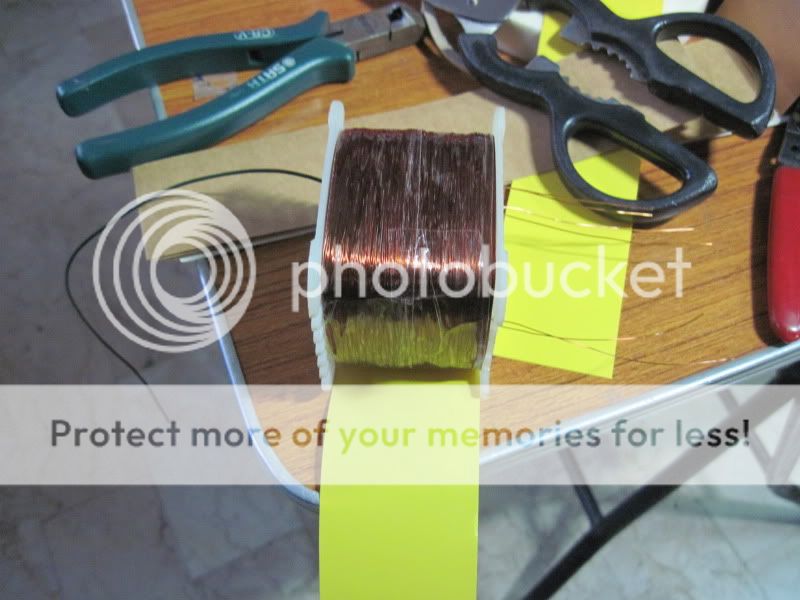
to break the boredom i decided to make a current transformer, ratio is 1:1000 so that an ampere on the primary causes 1mA to flow thr the seconday.....
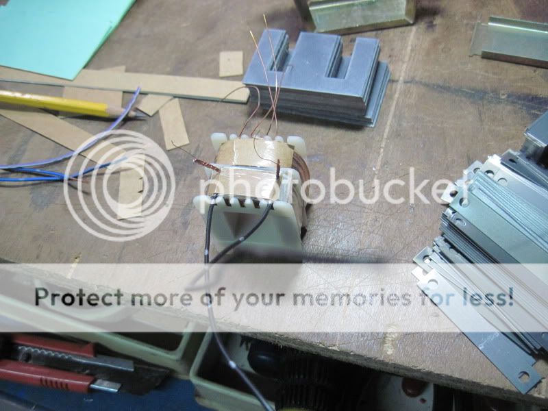
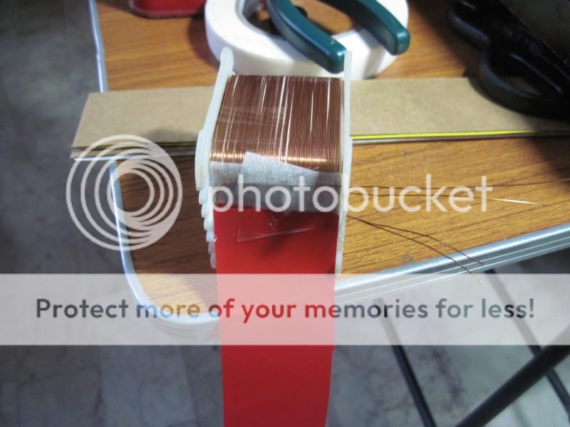
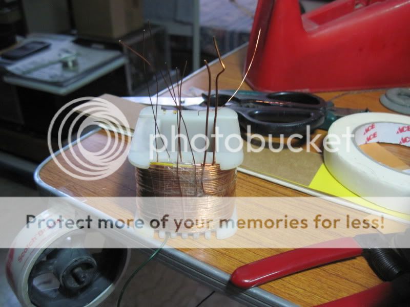
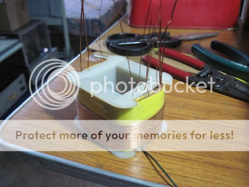
secondary coil uses 1000turns #33 wire on a 5/8 bobbin:
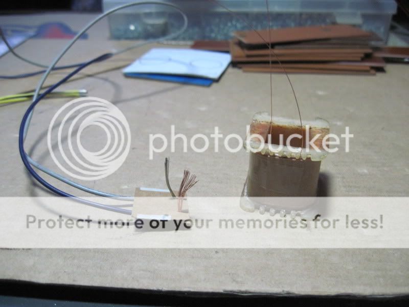
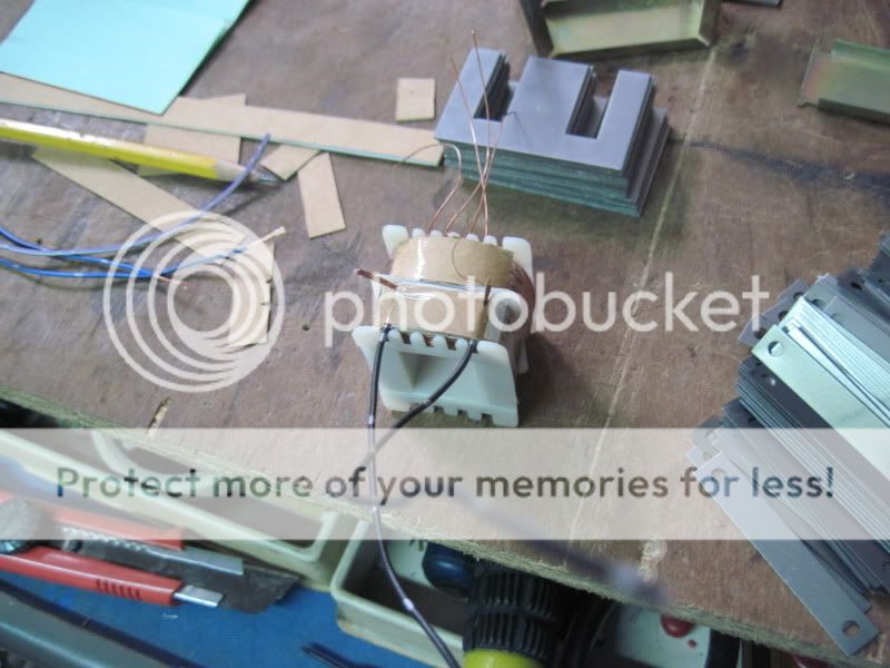
secondary leads ready for termination...
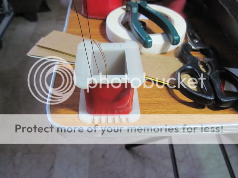
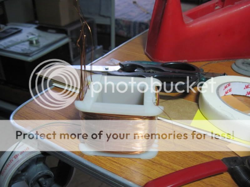
primary coil is a single turn of an insulated flat copper foil(from an atx psu traffo), pigtails soldered at both ends...
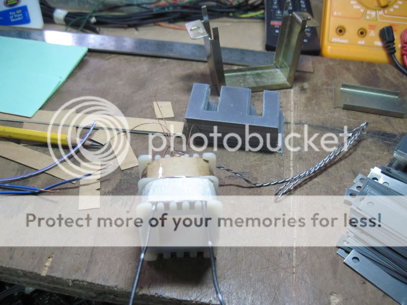
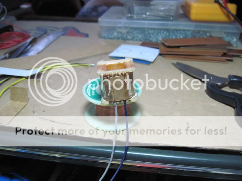
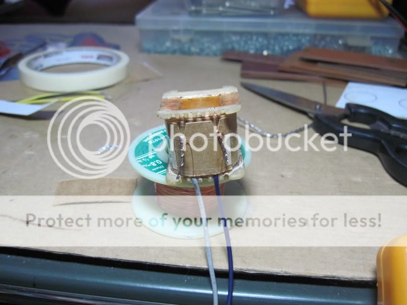
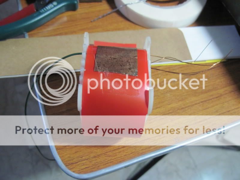
cores are installed next:
brackets installed:
i am going to use this ct to make a 0-10A analog meter using a dc 0-10mA panel meter.
secondary coil uses 1000turns #33 wire on a 5/8 bobbin:
secondary leads ready for termination...
primary coil is a single turn of an insulated flat copper foil(from an atx psu traffo), pigtails soldered at both ends...
cores are installed next:
brackets installed:
i am going to use this ct to make a 0-10A analog meter using a dc 0-10mA panel meter.
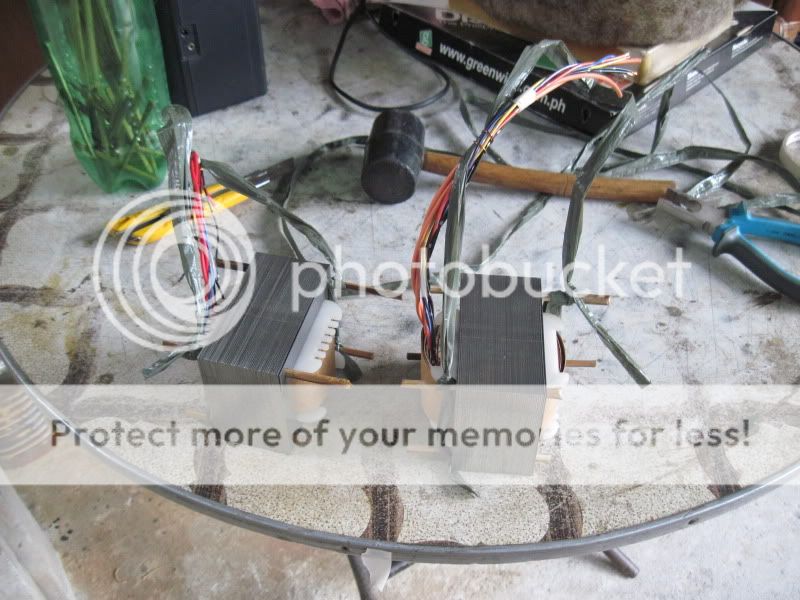
finished 2 power traffo's last night:
i used bamboo pegs on 4 holes of the traffo, slightly tight fit, so they don't fall off......
dipping in a pool of varnish, traffo is completely submerged, wait until bubbles disappear, do this several times:
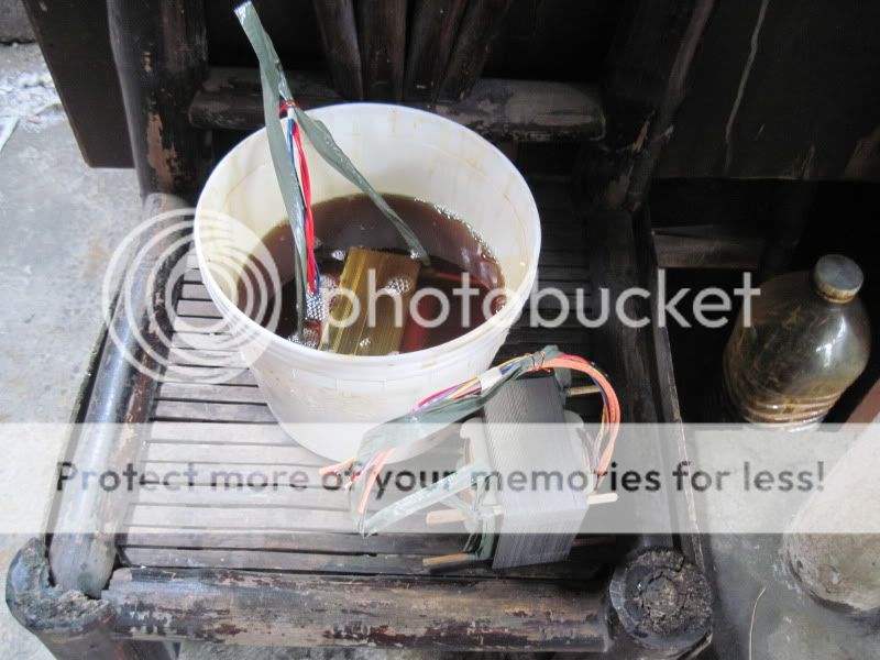
draining off excess varnish, again bamboo barbecue sticks are useful here:
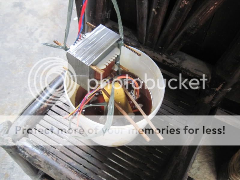
when dripping stops, traffos are hung out to dry, this takes 2 to 3 days:
i used bamboo pegs on 4 holes of the traffo, slightly tight fit, so they don't fall off......
dipping in a pool of varnish, traffo is completely submerged, wait until bubbles disappear, do this several times:
draining off excess varnish, again bamboo barbecue sticks are useful here:
when dripping stops, traffos are hung out to dry, this takes 2 to 3 days:
@ tony
this is trafo making art ............... truely great ....
Can u help me with foil winding for my smps txfr ..... It seems difficult how to insulate each layer from each other and how to bring out leads from the foil.....
regards
sekhar
this is trafo making art ............... truely great ....
Can u help me with foil winding for my smps txfr ..... It seems difficult how to insulate each layer from each other and how to bring out leads from the foil.....
regards
sekhar
thanks sekhar,
you can solder pigtails on each end of the copper foil, the pigtail can also be magnet wires of just hookup wires of sufficient size. you can use nitto tape to cover one side with slight overhang that you can fold-over the extra width to the other side....
you can solder pigtails on each end of the copper foil, the pigtail can also be magnet wires of just hookup wires of sufficient size. you can use nitto tape to cover one side with slight overhang that you can fold-over the extra width to the other side....
Hi Yugo,
i use a clear polyurethane air drying varnish, i do not have data on viscosity.....
i also used shellac flakes dissolved in denatured alcohol in my earlier builds.....
i use a clear polyurethane air drying varnish, i do not have data on viscosity.....
i also used shellac flakes dissolved in denatured alcohol in my earlier builds.....
Hi Yugo,
i also used shellac flakes dissolved in denatured alcohol in my earlier builds.....
...which means that polyurethane is better or simply easier to work with?
Regards,
Yugovitz
...which means that polyurethane is better or simply easier to work with?
Regards,
Yugovitz
and cheaper too....


i got a tube preamp power supply with burnt power supply transformer.
core was 1 1/8 stacked to 1inches, good thing, there was a lable on the leads showing specs,
1. 5volts@3A or 15 watts
2. 600volts ct. @0.050A or 30 watts
4. 15volts@1.5A or 22 watts
5. 10volts@0.3A or 3watts
total demand on the core was 70watts,
looking at RDH4, the core used can only support about 40 watts, so no wonder that the traffo burned out.
this is the burned out traffo:
so i decided to use a much bigger core, 1 1/4 x 1 1/2, this core can support power of 110 watts, so that we have
more than enough headroom....
1. computing for primary turns, Np = 1750/1.875 = 933 turns, @230volts primary,turns per volt = 933/230 or 4.13
2. computing for primary wire size, 110watts/230 = 0.478A, looking at the wire table, #26 wire seems suitable so i
am going to use that.
3. compute for secondary wire sizes;
3.1 300volt winding, i will use just a single winding and convert the rectifier to be assiste by silicon
rectifiers, this will result in lesser transformer heating. so here i choose #30 wire,
3.2 15volt winding, i choose #20 wire.
3.3 10volt winding, i choose #26 wire.
3.4 5volt winding, i choose #18 wire
the new transformer will have bigger windows so that bigger wire sizes can be used.
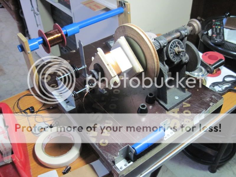
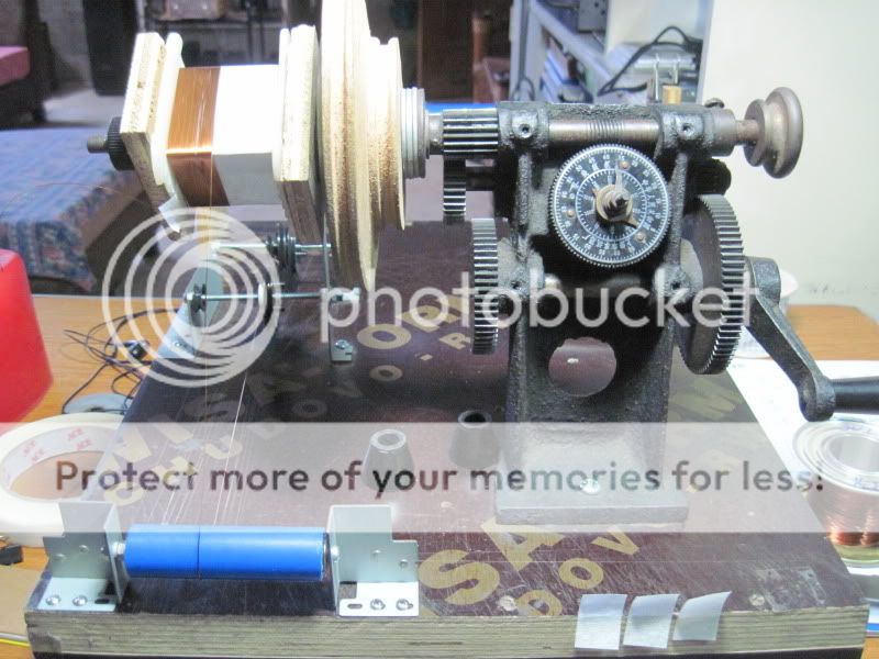
winding primary coil:
installing the electrostatic sheild:

winding the secondary coils:
completed transformer:
side by side with the burnt traffo:
core was 1 1/8 stacked to 1inches, good thing, there was a lable on the leads showing specs,
1. 5volts@3A or 15 watts
2. 600volts ct. @0.050A or 30 watts
4. 15volts@1.5A or 22 watts
5. 10volts@0.3A or 3watts
total demand on the core was 70watts,
looking at RDH4, the core used can only support about 40 watts, so no wonder that the traffo burned out.
this is the burned out traffo:
so i decided to use a much bigger core, 1 1/4 x 1 1/2, this core can support power of 110 watts, so that we have
more than enough headroom....
1. computing for primary turns, Np = 1750/1.875 = 933 turns, @230volts primary,turns per volt = 933/230 or 4.13
2. computing for primary wire size, 110watts/230 = 0.478A, looking at the wire table, #26 wire seems suitable so i
am going to use that.
3. compute for secondary wire sizes;
3.1 300volt winding, i will use just a single winding and convert the rectifier to be assiste by silicon
rectifiers, this will result in lesser transformer heating. so here i choose #30 wire,
3.2 15volt winding, i choose #20 wire.
3.3 10volt winding, i choose #26 wire.
3.4 5volt winding, i choose #18 wire
the new transformer will have bigger windows so that bigger wire sizes can be used.
winding primary coil:
installing the electrostatic sheild:
winding the secondary coils:
completed transformer:
side by side with the burnt traffo:
Each winding can have it's own VA rating........... there was a lable on the leads showing specs,
1. 5volts@3A or 15 watts
2. 600volts ct. @0.050A or 30 watts
4. 15volts@1.5A or 22 watts
5. 10volts@0.3A or 3watts
total demand on the core was 70watts,
looking at RDH4, the core used can only support about 40 watts, so no wonder that the traffo burned out.
The total VA rating for the transformer can be much less than the total of the VA ratings for the secondaries.
It can be a 40VA transformer and still have all those winding ratings.
It is up to the designer/builder to ensure that the transformer is run within it's ratings.
the test for transformer builds is surviveability in actual use.....the fact that the old traffo failed is proof that the design was flawed at the start....
- Home
- Amplifiers
- Power Supplies
- Tony's latest traffo DIY build