WOW, looks really nice! You did that by hand?
Let me ask you or anyone who know:
I am trying to build a SMPS transformer and when we have done the calculations in order to know the best AWG wire and number of strands, what is the criteria/rule/procedure that we must follow in order to make all the winding fit in one layer two for the primary winding, then for the secondary?
For example, look at the picture that nazirdigi has posted. Imagine that we have done one complete layer but we didn't finish doing the primary size because there still some turns remaining. Finishing those remaining turns, we see that has occupied only half of the bobbin, that means 1 layer plus half of the second. Of course that cannot stay like that because we must have attention to the proximity effect, RAC/RDC (or vice-versa, don't remember now), leakage flux, etc.
Kind regards.
hi tony,
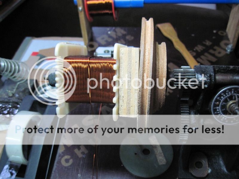
is this correct or not?
i make the bobbin with epoxy pcb board.
i start wind secondary first.
if first layer complete what insulation material should i use?
In one wire there is a little scratch on top of the wire,(.3mm by .4mm)(the enamel is removed), my screw driver scratched. is it ok or i have to replace the hole wire with new one?
can i add transformer varnish to the scratch area?
is this insulation paper is good for layer separating?
what material used to separate between primary and secondary?
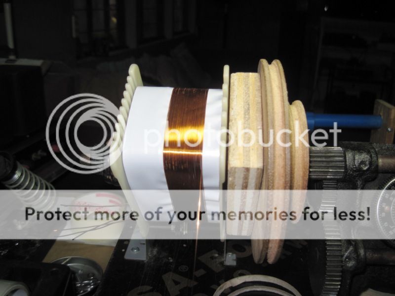
you can use masking tape or cellophane tape on scratched part of the wire....
fish paper like what you have there is good for interlayer separators...
WOW, looks really nice! You did that by hand?
Let me ask you or anyone who know:
I am trying to build a SMPS transformer and when we have done the calculations in order to know the best AWG wire and number of strands, what is the criteria/rule/procedure that we must follow in order to make all the winding fit in one layer two for the primary winding, then for the secondary?
For example, look at the picture that nazirdigi has posted. Imagine that we have done one complete layer but we didn't finish doing the primary size because there still some turns remaining. Finishing those remaining turns, we see that has occupied only half of the bobbin, that means 1 layer plus half of the second. Of course that cannot stay like that because we must have attention to the proximity effect, RAC/RDC (or vice-versa, don't remember now), leakage flux, etc.
Kind regards.
from what i have seen dismantling smps traffos, wires are shorter and so can be smaller in diameter.....entirely different than power transformers using silicon steel EI's.....smps also uses wide copper strips to help in the skin effect problems....
I see, but the point is that doesn't mean that what I have asked don't apply, even with shorter wires.
you can use masking tape or cellophane tape on scratched part of the wire....
fish paper like what you have there is good for interlayer separators...
thanks tony for the reply.
hi tony,
is it fish paper one side aluminium color and other side brown color paper.
so fish paper use to separate primary and secondary?
can u post a image of the good insulator separators. and fish paper.
is it fish paper one side aluminium color and other side brown color paper.
so fish paper use to separate primary and secondary?
can u post a image of the good insulator separators. and fish paper.
WOW, looks really nice! You did that by hand?
Let me ask you or anyone who know:
I am trying to build a SMPS transformer and when we have done the calculations in order to know the best AWG wire and number of strands, what is the criteria/rule/procedure that we must follow in order to make all the winding fit in one layer two for the primary winding, then for the secondary?
For example, look at the picture that nazirdigi has posted. Imagine that we have done one complete layer but we didn't finish doing the primary size because there still some turns remaining. Finishing those remaining turns, we see that has occupied only half of the bobbin, that means 1 layer plus half of the second. Of course that cannot stay like that because we must have attention to the proximity effect, RAC/RDC (or vice-versa, don't remember now), leakage flux, etc.
Kind regards.
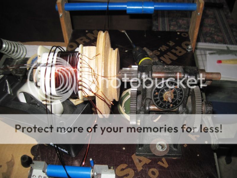
thanks for the comment,
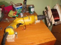
i use drill machine to wind.
in the image i remove the drill machine from my table.
hi tony,
is it fish paper one side aluminium color and other side brown color paper.
so fish paper use to separate primary and secondary?
can u post a image of the good insulator separators. and fish paper.
something like this:
An externally hosted image should be here but it was not working when we last tested it.
bifillar winding
winding the primary coil:
winding auxilliary coils:
bifillar secondaries:
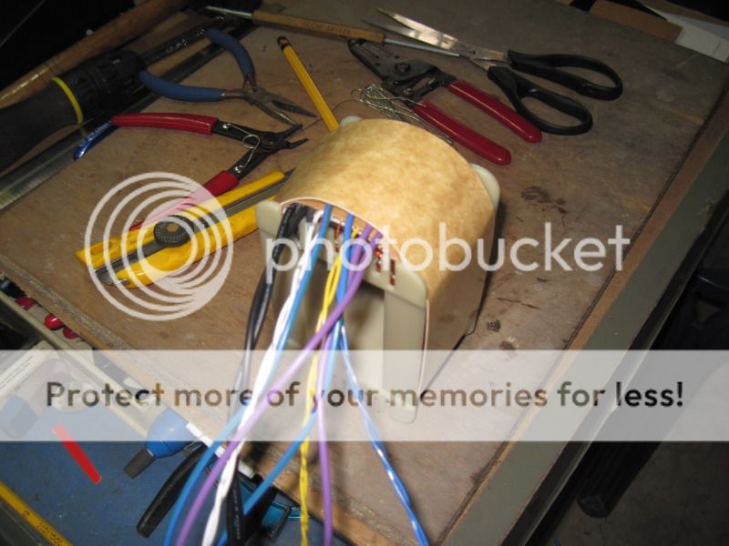
terminating pigtails:

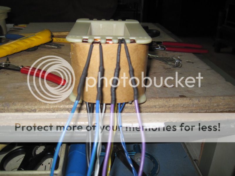
completed coils:
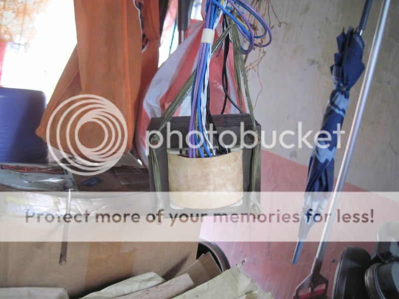
after varnish dipping hung out to dry:
winding the primary coil:
winding auxilliary coils:
bifillar secondaries:
terminating pigtails:
completed coils:
after varnish dipping hung out to dry:
from the net, they are from china, materials available for sale in Manila are all imported from china....
Amazing work Tony. Can I ask you something? Your winding machine is manual, right? So, with one hand you give hand crank and with the other you do tension?
Another thing that I want to ask, but I did it before, and I'll ask again because no one answered exactly to my question, but now in other words.
@Tony or anyone else, when winding the trafo, if the turns, for example, of the primary finish at the middle of the bobbin/former, what you do? Recalculate the wire size in order to give more adequate fitting to the bobbin?
Amazing work Tony. Can I ask you something? Your winding machine is manual, right? So, with one hand you give hand crank and with the other you do tension?
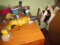
yes, i had a wooden pulley made which i use to turn the bobbin when winding, my wife assist me in this instance with the wire feeding these big diameter wires....at other times i do it alone....😀
Another thing that I want to ask, but I did it before, and I'll ask again because no one answered exactly to my question, but now in other words.
@Tony or anyone else, when winding the trafo, if the turns, for example, of the primary finish at the middle of the bobbin/former, what you do? Recalculate the wire size in order to give more adequate fitting to the bobbin?
yes, that happens a lot of times, you have 3 choices, first is just go with it, the space can be used for auxilliary windings......second is just fill up the layer and recompute the secondary windings, you can do this when unsure about the quality of your core material.....third is to forgo and use the last filled up layer and then recompute for the secondary turns based on actual primary winding, this can be done if your core material is good quality like M6 goss steel.....
i hope this answers your question....😀
The First I got it. The Second, what you mean is to fill up, with extra turns, the remaining layer (starting from where the turns have stopped) and then recompute the secondary windings and the Third, is almost the contrary, meaning, instead of filling up with extra turns, we remove the turns that have finished at the middle of the bobbin/former, in order to use only the turns that have filled the last layer. Then recompute again the secondary turns?
Is that it?
I am sorry for repeating, but is to be sure!
Kind regards.
Is that it?
I am sorry for repeating, but is to be sure!
Kind regards.
you got it....
So that was about mains transformer ( with CRGO) and not ferrite transformer. am I right?
To my knowledge, with ferrite core transformers number of turns and inductance are kept unchanged. But multiple primary are used for better coupling and getting leakage inductance low. pl. correct me if not so.
sir tony,i read your thread and interest me very much but for now im not ready to diy a transformer can u send me your email add? here is mine, cerdenia.luisito at yahoo dot com thank's, more power.🙂
Last edited by a moderator:


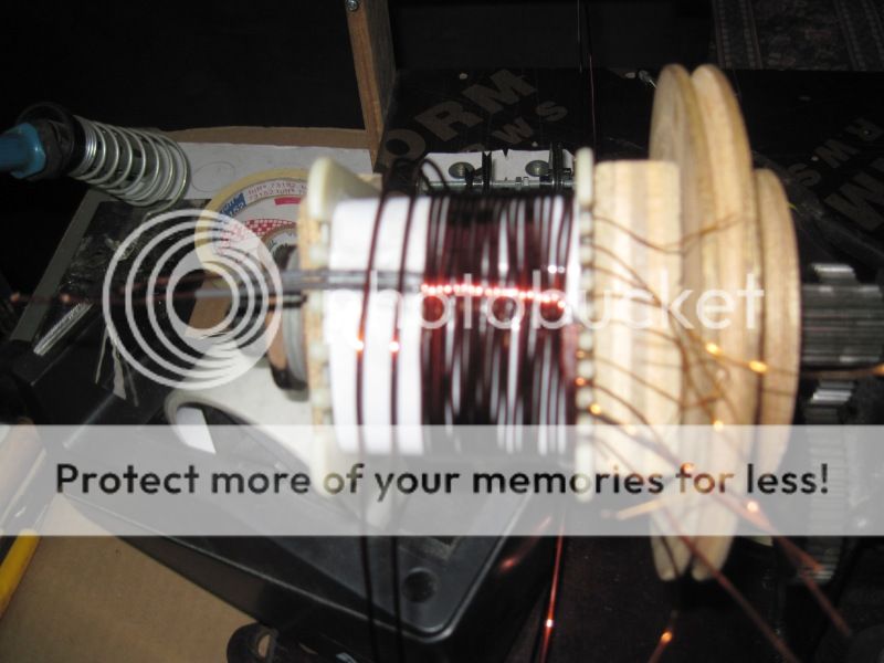
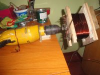
hi istpyro and tony,
this is how i wind with the drill machine.
looks nice , do u have turn counter too ?
- Home
- Amplifiers
- Power Supplies
- Tony's latest traffo DIY build