As I see online it is a known fact that germanium diodes have an average voltage drop of about 0.3V. Mine are stated as germanium diodes, look identically to one, and have the same Vf 🙂 so they are germanium diodes for sure.
BAT41 tested almost the same Vf. Are they good replacements in my circuit?
BAT41 tested almost the same Vf. Are they good replacements in my circuit?
That sounds high for a true germanium although they do vary between device types. I'll measure some of mine later.
Finally got to measure a few and yes, they do seem to have a higher forward voltage than I imagined. Around 250 to 350 millivolts.
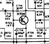
H704 is a 2SC1318 with a gain of 85-170 or 120-240 and Ic of 500mA.
I can't find a suitable transistor with 500mA rating so I wanted to see if I can replace it with a 50mA device.
Looking at the schematic there's R729 100 ohm resistor in the emitter of H704, and in the parts list it is stated as a 0.25W resistor. That means that no more than 50mA of current can flow through it as that would be the maximum spec for it's power rating. And maybe even less than 50mA as it would be operated at the outer limit of it's rating. Is this correct?
Attachments
H704 is a 2SC1318 with a gain of 85-170 or 120-240 and Ic of 500mA.
I can't find a suitable transistor with 500mA rating so I wanted to see if I can replace it with a 50mA device.
2SC1318
Is this correct?
Only up to a point. That's for steady state DC conditions. A 50ma device is far to small for that location (VAS voltage amplifier stage) because of any transient current and the possibility of secondary breakdown. The 2SC1318 has a 1000ma peak capability. Its there for a reason 🙂
Are you sure they are not poorly manufactured devices? Did you buy from them?
Whenever I order from them I ask for the Manufacturer of that part.
You are right, sometimes they answer "ISC" or CDIL, etc. But sometimes they still have the original part.
Ulf
You are right, sometimes they answer "ISC" or CDIL, etc. But sometimes they still have the original part.
Ulf
I asked them and will wait for an answer before I order.
Also I saw that they have 2SC1384/2SA684 that I need. Will wait for a response.
Thank you.
Also I saw that they have 2SC1384/2SA684 that I need. Will wait for a response.
Thank you.
I decided I will replace the 2SD315 output transistors with TIP41C just for testing purposes on first power up 🙂
I don't want to risk my precious rare 2SD315. I like the way they look on the heatsink.
I can get 8 TIP41C's for 2 bucks so just some more work involved.
I don't want to risk my precious rare 2SD315. I like the way they look on the heatsink.
I can get 8 TIP41C's for 2 bucks so just some more work involved.
I would be careful changing transistors.
If you aren't careful you can quickly go from a stable amplifier to an oscillating one.
Even changing to new transistors of the same type can cause problems sometimes.
I bought a 1980's Maplin 225WRMS amplifier with MJ2955/2N3055 outputs missing.
So I bought in new ones, fitted them and the amplifier oscillated very badly.
I tested the new transistors on a semiconductor analyser and the gain was much more than the spec of the original transistors.
Personally I would have just replaced electrolytic's and left it there.
The original transistors from the amp are rated for a gain of 100-200. Tip41 is under 100.
Even if it were higher, I still wouldn't expose the stock transistors to my restore job 🙂
I prefer to blow a 30 cent part than a 10$ one.
And this is the purpose of diy, to tinker and sometimes mess up and learn from mistakes.
TIP41 would be installed to check that everything else is working and I haven't done a mistake that would cost me my original output transistors.
I've got a lot of Fairchild TIP41C that seem to be running gains of ~400. They saturate in the original circuit as VAS (voltage amplifier stage). I'm not sure excess gain would be a problem in emitter followers (output transistors).The original transistors from the amp are rated for a gain of 100-200. Tip41 is under 100.
When replacing 200 khz Ft transistors with 2 mhz, you have to put disc capacitors on the driver transistors (~50 pf) to slow things down if they oscillate. b-e or b-c. At least that is what dynaco did. Another thing is checking idle current on O.T.'s hot - old 1970 transistors had internal resistance, new ones don't and need .33 ohms in the emitter circuit (roughly) . At least that is true for RCA 2n3055 and derivatives.
Last edited:
You might find this thread interesting as it was an amp of similar vintage. All that was needed was replacement of transistors. Unfortunately it didn't have a happy ending 🙁 and all due to the characteristics of modern devices being different.
http://www.diyaudio.com/forums/solid-state/259602-kenwood-ka-3500-my-blooper.html#post4014765
Enjoy 🙂
http://www.diyaudio.com/forums/solid-state/259602-kenwood-ka-3500-my-blooper.html#post4014765
Enjoy 🙂
- Status
- Not open for further replies.
- Home
- Amplifiers
- Solid State
- to92 transistor replacement