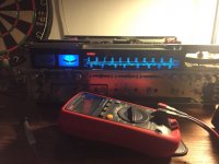
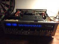
Why did you replace all the resistors but not the trimpots? Those, if anything, could benefit from a replacement. Old trimpots tend to work poorly.
Oh tell me about it.
I had the lightbulb setup stored away in the basement and I was feeling a bit lazy. I do trusted myself with each soldering but there was a maturity voice in the back of my head screaming to move my *** and get the lightbulb.
Before I pushed the switch I was thinking that it would be very hard for me to start troubleshooting if indeed the bulb is very bright. I feel exhausted after all the work I've done. But yes... it was a special moment 🙂
Why did you replace all the resistors but not the trimpots? Those, if anything, could benefit from a replacement. Old trimpots tend to work poorly.
I used like quarter of a can of deoxit on those 8 trimpots. They are working really smooth now, and also I've tested their ranges and I found no dead spots.
They are very convenient for position and I couldn't be bothered to try and install something else with the same footprint.
Well done!
You obviously know what you are doing! 😀
Thank you Sir!
I am having a bit of an issue, not big but nevertheless it's troubling me a bit.
It seems that the rear left channel has a larger swing than the rest. I can dial it back from the balance slider on front. I have to offset that a bit to get it in alignment with the rest of the pack.
I will try and see what's happening in the low signal stages.
The only issue I'm having is that one of the 4 channels is a bit higher amplitude.
I traced it to the preamp board.
On the buffer board on JD01 - JD08 all signals are equal in amplitude (buffer is gain 1).
On the Tone amp board JE04 - JE02 - JE03 are equal, JE01 is higher.
I traced the issue to the balance pot board.
I measured the resistors I installed and they are all 3.3k. Signal going into the slider board is ok for all 4 channels, signal coming out is higher for one channel. With the sliders in their center position.
So it seems that one of the slider pots has an offset.
I will leave it at that and set it for equal signal after I assemble everything.
Didn't notice this before as I didn't measure anything in the amp.
So ... I'm happy with this result 🙂
Forgot to mention that I've replaced the output transistors with MJE15032 (couldn't find mje15030). I set the bias at 15mA as per manual. I think that's per pair. Could I/should I up it?
Right now I made some listening tests at higher volume (the kind I don't usually listen to), and the output transistors are barely warm after 10 minutes. In fact I don't think they are colder than my skin temp.
The psu heatsink is running on the hot side, right where I can barely keep my fingers on the top of it. But that happened before. I haven't replaced that one, it's still 2SD315. I have tip41C but I don't think I'm going in again...
I would keep the bias at the recommended level simply because that is what the heatsinks and more importantly the bias network will have been designed for. The theoretical optimum is considerably higher but that might cause problems.
Looks good and it looks like you got the illumination pretty even which can be trick with LED's 

I had an issue with the fact that the left side dials were brighter than the tuner dial. I had to up the resistance on those to make it even.
Here you can see the difference:

This is how the LED fixture looks like:

The incandescent bulbs were powered by AC so I got vlmw42 leds that have a diode across them and put them cathode to cathode. I do sense some 100hz flicker with the corner of my eyes without the plastic faceplate but otherwise it's great, I can't notice anything.
Here you can see the difference:

This is how the LED fixture looks like:

The incandescent bulbs were powered by AC so I got vlmw42 leds that have a diode across them and put them cathode to cathode. I do sense some 100hz flicker with the corner of my eyes without the plastic faceplate but otherwise it's great, I can't notice anything.
Last edited:
I will botch some parts on the back of the PS board if I find the flicker annoying. Adding caps was too complicated for the light fixtures. I only noticed them while the LEDs were exposed and only with the corner of my eye. With the plastic front plate cover on I didn't notice anything.
Also if I do make it DC then I'll only have one LED lit from the two in the setup depending on which way the current flows 🙂 right now each led covers half cycle.
Yes, a bridge will double the flicker rate from 50Hz to 100Hz.
Think about the settings you adopt for your Monitor?
Do you set the screen refresh to 50Hz or 70Hz or faster?
The sideways sensitivity to flicker is an evolutionary attribute to prevent us getting eaten by animals creeping in, stealthily for the kill.
Think about the settings you adopt for your Monitor?
Do you set the screen refresh to 50Hz or 70Hz or faster?
The sideways sensitivity to flicker is an evolutionary attribute to prevent us getting eaten by animals creeping in, stealthily for the kill.
The sideways sensitivity to flicker is an evolutionary attribute to prevent us getting eaten by animals creeping in, stealthily for the kill.
Yes I know that, it was exactly what I thought about after I noticed the flickering 😛
Leds draw such a minute current that you could run them off the main rails with a simple two transistor constant current sink. That removes the 'sound to light' or 'disco lights' effect when the amp is pumping current.
http://www.diyaudio.com/forums/powe...-high-voltage-into-constant-current-sink.html
http://www.diyaudio.com/forums/powe...-high-voltage-into-constant-current-sink.html
Think about the settings you adopt for your Monitor?
Do you set the screen refresh to 50Hz or 70Hz or faster?.
I had forgotten all about this. I was really sensitive to screen flicker. This was over 10 years ago. Man, how I don't miss CRTs! 😉
A few observations:
Is it normal for the bias to not be steady? It kind of jumps between 13-17mA when set at 15mA. I noticed this behaviour before the restore. I saw this after one hour of continuous use at a decent volume.
Another issue is that it still seems to be dropping the right channel only now. I left it playing in the background now at low level and one channel was out. I tried turning the volume high but didn't got the channel back. I had to turn off the unit then turn it back on and it works now. Happened 3 times already.
I also used croc pliers to squese the wire on the connecting posts. Didn't do this on all connections, but did it on buffer board I think and some on the tone/preamp board. I tried soldering but it's really hard as there's many wires in the way and solder doesn't stick, even with flux applied.
- Status
- Not open for further replies.
- Home
- Amplifiers
- Solid State
- to92 transistor replacement
