The overall sound is very nice and the stereo separation is better than anything I heard before. But I only had a ta2020 amp and a tda7297 amp.
Bias altering and drifting is absolutely normal but it shouldn't 'suddenly' alter (like throwing a switch). If it does then that points to possible instability.
You need to set the scope up to monitor the input to the channel dropping out and see whether its front end or power amp trouble.
You need to set the scope up to monitor the input to the channel dropping out and see whether its front end or power amp trouble.
The bias jumps around constantly. It isn't stable for one second.. It constantly varies between 13-17mA. I tried upping it at 20mA and the same, 18-22mA jumps around. Also at 10mA. On all 4 channels. But I remember it doing the same before I touched it. The first thing I did when I got it was to adjust the bias.
I will try next time to see if I get the channel back by turning up the volume as now I had it low from the sound-source, I just noticed. If it comes back then it's sure the same as before and the only things left are the wiring and the two 2SC1384/2SA684 pairs (and the SV-3A diodes and varistors).
Could be a new problem thou. If it happens again I will take off the case and scope the right channel until it drops out. I think I need to leave it at low volume to replicate the issue. Right now it was like barely audible when it happened. I have buttons for the Main/Remote speakers, and I can turn off completely the speakers. Doing that didn't bring back the sound. I had to cycle the power. At power on it started normal.
The bias you will have to look into. Just a thought, if the bias generator isn't super stable (meaning its rail dependent to some extent) then mains fluctuations will reflect in the bias current. It should be immune but as its of a design of yesteryear when such things weren't looked at as closely perhaps, well you never know...... just a though as I say.
Those old trimmers are usually a source of trouble. They tend to be very unstable. They MUST be lubricated to be expected to work at all.
Bias usually moves around a bit. It is most likely not a big deal.
Bias usually moves around a bit. It is most likely not a big deal.
Could the bias be affected by H710-H713? I hand checked those and they were cool at moderate listening levels.
Those old trimmers are usually a source of trouble. They tend to be very unstable. They MUST be lubricated to be expected to work at all.
Bias usually moves around a bit. It is most likely not a big deal.
I used some type of deoxit that leaves a thin film of lubricant. The pots move real smooth, I can adjust them precisely with my fingers. I think I remember when I restored a Sansui AU-6500, the bias was still jumping but no more than 1mA. Here it's like 2-3mA. I noticed at times it would ramp up a bit to like 20mA but come back down. Especially while adjusting.
I'm almost sure it's a matter of cable connection to the posts. But I need to snoop around a bit with the scope and see exactly what's happening. A quick finger test might target the issue faster on the low level boards.
Last edited:
Could the bias be affected by H710-H713? I hand checked those and they were cool at moderate listening levels.
They certainly affect the bias... they are crucial... but they wouldn't cause it to jump about unless they were faulty in some peculiar way.
If the bias jumps about on its own then I would hook a second meter up to the rail and monitor that along with the bias. Does the bias alter as the rail alters (due to normal mains fluctuations ?
As others have said, the pots can be trouble, so you at least need to satisfy yourself they are OK.
the bias voltage should move very slowly as the temperatures inside the various semiconductors change.
there should be no sudden jumps.
The output offset does move quickly. A typical offset changes continuously over a small range maybe +-1mV, or more often +-2 to 3mV.
there should be no sudden jumps.
The output offset does move quickly. A typical offset changes continuously over a small range maybe +-1mV, or more often +-2 to 3mV.
This is cap coupled to the speakers so I didn't have to check the DC offset.
I will look into the matter. The same behaviour on all 4 channels so it must be something common to all. I'd say H710-H713 as they have been around for some time.
Also there's that varistor... It's marked as a diode on the schematic, and when I took it off it didn't show any distinctive mark for positioning. On the diode test it tested both ways and Vf varied if I kept my finger on it but didn't know exactly how to put it back in. I figured it was either way since it tested the same both ways. It might have had a larger Vf one way than the other but could have been the temperature drift from handling it while testing.
The same behaviour on all 4 channels so it must be something common to all.
Yes, the incoming mains. Try switching a heater or something that uses a lot of current on and seeing if the bias alters the instant you throw the switch.
Could the amps be intermittently going into instability and back to stable operation?
This might show as step changes in bias voltage.
This might show as step changes in bias voltage.
Yes, the incoming mains. Try switching a heater or something that uses a lot of current on and seeing if the bias alters the instant you throw the switch.
Ok, I will try this tonight and see what's happening.
Would it benefit big time to regulate the power? Shouldn't be that hard to squeeze a pcb in. But that would need some thinking.
I guess the fact that I have a dropping channel doesn't have anything to do with the jumping bias?
I will look for oscillation tonight. Any good references on what to look for more exactly? Or how to setup the test?
Could the amps be intermittently going into instability and back to stable operation?
This might show as step changes in bias voltage.
It could definitely be something like that with all the transistors that have been swapped.
Ok, I will try this tonight and see what's happening.
Would it benefit big time to regulate the power? Shouldn't be that hard to squeeze a pcb in. But that would need some thinking.
I guess the fact that I have a dropping channel doesn't have anything to do with the jumping bias?
I will look for oscillation tonight. Any good references on what to look for more exactly? Or how to setup the test?
Just scope the output both on and off load. See if anything shows as you monitor and observe the bias change.
At first I monitored DC in on the output boards and it is jumping between 48-51VDC but not that sudden. There's some action in the decimal area, jumping constantly 200-300mV up and down.
When I first connected the dmm there was 48.50VDC or so, then it climbed to 50.50V and it jumps around between 50.20V and 50.80V. Sometimes it dips to 48.60V or so but mostly 50.50V
When I first connected the dmm there was 48.50VDC or so, then it climbed to 50.50V and it jumps around between 50.20V and 50.80V. Sometimes it dips to 48.60V or so but mostly 50.50V
I'll try some more to hunt for the dropping channel this weekend. Also I will use the scope to check for oscillation. But even at 22-23mA bias on all channels the metal tab of the transistors is at 27.7 degrees C at normal listening level. Almost background music, but a bit more.
Would this fluctuation call for regulation? Bias jumps about 1mA constantly.
The amp is 2x30W at max, so with 50% efficiency that would be 120W? At 50V that would be what...2.5A or so? I guess a 5A regulator would do here. I could use a LT1084 or so. With about 2-3V lost in the regulator I can feed a steady 45-46V or so. Would that be enough for the output stage? There's no mentioning of transformer output voltage in the manual. But considering that the main cap was 55VDC rated I presume that higher than 38.88VAC it wasn't. I'm measuring 40VAC at the fuses and 39.3VAC or so at the bridge input (crappy wiring?). I presume it is higher because of 220VAC (way back) vs 230VAC (now). 38.88VAC would be the absolute limit that the capacitor would be rated for so I presume a safer 35VAC would be the actual rating? That would give me a good 7VDC to burn as heat. Since it's working now it would surely work regulated at lower 3-4V than now. I can't measure exactly as it's under load and I presume disconnected would measure more.
At max 3V lost as heat at 3A (9W, at max volume) the regulator could release that into the case. I don't know how to solve the needed room for the additional caps.
More than likely it's just poorly regulated bias. If it's not oscillating don't sweat it. If you don't have a scope, locate the output zobel. It's a series RC hanging off the output in parallel with the load. Typical values are 0.1uF and 10 ohms. It provides a load for the amp at high frequency, where voice coil inductance causes speaker impedance to climb. If you have high frequency oscillation, it will conduct current and the resistor will heat up. No heat = no problem.
Regulating the main rail would help - but you'd be surprised by what you'd have to drop it to. I'll bet it drops to 30V or so under full load - and regulating it "down" by only 3 to 7V would not be enough. If you wanted to put in a regulated supply you would want to up the capacity of the trafo. Too much trouble to go to, IMO.
Regulating the main rail would help - but you'd be surprised by what you'd have to drop it to. I'll bet it drops to 30V or so under full load - and regulating it "down" by only 3 to 7V would not be enough. If you wanted to put in a regulated supply you would want to up the capacity of the trafo. Too much trouble to go to, IMO.
I will check to see how low it goes at full power.
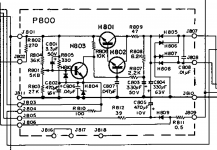
Right now I was thinking about that 220VAC vs 230VAC and decided to test the low current power supply. And ... yes...not great. 43.3VAC found on it. Rectified that's 61.22VDC. The output of the power supply should be 35VC so that's a 26V drop on the power supply.
I measured the filtering R809 and it has a 8.9V drop on it, putting out 2.4W of heat. In the datasheet that is a 47ohm/3W resistor, but on board was a 33ohm/5W resistor. I mixed them because I wasn't paying attention and now there's a 33ohm/3W resistor on the board, with increased voltage across it 🙂 It's staying at a "warm" 145 degrees C. And it's right next to the large heatsink.
Great.
I measured the current draw (across R809) and is about 270mA right now. Way high for buffer + preamp. But those are not the only things drawing current.
On R802 I can see how much P600 + PL01 boards are sucking and that's about 57mA for doing nothing all day everyday. Those boards are the Dolby board and Dolby Tone&Meter board. Don't need those so I'll just disconnect them from J802 connecting point on the power supply board. That should give me a cooler 213mA draw.
R805 has 64mA going through it but that's needed for regulation I think and there's a line going to some of the small bulbs (stereo fm/am etc). R806 and R804 have negligible current, sub 1mA. That's a total of 148mA or so for the rest of the amp.
P500 board draws 0.5mA.
Ta7129 IC draws 3.5mA, so that's 7mA because there are two of them.
Phase inverters from the output stage draw about 3mA in total, measured.
Preamp draws 10mA measured.
Buffer can't be measured as it has no resistor in series on the input. I measured the higher wattage 2.2k resistors. 11mA through one and there's 4 of them so that's at least 45mA on the board.
That leaves about 80mA. I don't understand where that current is going to.
Is it something that I'm missing?
Attachments
Last edited:
I just realised that I did the math thinking that R809 is after H801 but in fact it is before it.
/fail
I'll just take out P600+PL01 and call it a day. That should be good for the rating of R809 at 1.5W.
/fail
I'll just take out P600+PL01 and call it a day. That should be good for the rating of R809 at 1.5W.
Last edited:
I will look at the output with the oscilloscope. I might design a new regulated supply altogether.
There's not much to be done, just 35VDC output. There's hardly the need for 7W.
The Zobel resistors are stone cold (R763-R766).
The transformer looks hefty, quite large for 2x30W output. I have some 100W 8ohm resistors that I'll use to see how much the power supply will dip, but should hold by the looks of the transformer. I will also check the voltage drop on the wiring. I replaced all wiring from bridge to each board and large cap. There's some wiring left from the bridge to some wiring posts where it meets the leads of the transformer.
There's not much to be done, just 35VDC output. There's hardly the need for 7W.
More than likely it's just poorly regulated bias. If it's not oscillating don't sweat it. If you don't have a scope, locate the output zobel. It's a series RC hanging off the output in parallel with the load. Typical values are 0.1uF and 10 ohms. It provides a load for the amp at high frequency, where voice coil inductance causes speaker impedance to climb. If you have high frequency oscillation, it will conduct current and the resistor will heat up. No heat = no problem.
Regulating the main rail would help - but you'd be surprised by what you'd have to drop it to. I'll bet it drops to 30V or so under full load - and regulating it "down" by only 3 to 7V would not be enough. If you wanted to put in a regulated supply you would want to up the capacity of the trafo. Too much trouble to go to, IMO.
The Zobel resistors are stone cold (R763-R766).
The transformer looks hefty, quite large for 2x30W output. I have some 100W 8ohm resistors that I'll use to see how much the power supply will dip, but should hold by the looks of the transformer. I will also check the voltage drop on the wiring. I replaced all wiring from bridge to each board and large cap. There's some wiring left from the bridge to some wiring posts where it meets the leads of the transformer.
- Status
- Not open for further replies.
- Home
- Amplifiers
- Solid State
- to92 transistor replacement