I would appreciate your demo. And based on my findings shown in my post, what might the woofer crossover slope be?No, the woofer would roll off faster because the mid connection between the inductors disrupts them. I can arrange a basic demonstration if Henry would like.
Not much more steep at the start, because this passive LRLR filter isn't the resonant kind. However it is second order so you can expect to see up to 12dB/octave. There would be a phase difference between the woofers but most likely within allowable limits so there should not be a problem between them.
Since woofers are not resistors it won't be exactly like this. Maybe less than this example using your component values..

Since woofers are not resistors it won't be exactly like this. Maybe less than this example using your component values..
Thanks for the demo. And I just want to know if I understand the filter orders in the P6 correctly. Is the tweeter a 3rd order, the mid range a 1st order and the woofer a 2nd order?
Last edited:
Yes, you are reading it correctly.. it may vary a little due to the drivers not being resistors.Is the tweeter a 3rd order, the mid range a 1st order and the woofer a 2nd order?
Inductor/resistor (x2)What does LRLR filter mean?
It might be interesting to see the effect of driver inductance on the low pass slope by modelling the upper mid-bass as 5Ω in series with 0.41mH, which are the approximate values for the B&W kevlar driver.Since woofers are not resistors it won't be exactly like this. Maybe less than this example using your component values..
Does this at all relate to what I'm planning to do? FWIW I also have B&W N803 which have the fst kevlar mid range driver and its filter has L1 1.45mH, L2 0.5mH and L3 1.6mH and also has four resistors and five capacitors. What B&W speaker has the kevlar mid range with 5ohm and 0.41mH?It might be interesting to see the effect of driver inductance on the low pass slope by modelling the upper mid-bass as 5Ω in series with 0.41mH, which are the approximate values for the B&W kevlar driver.
Last edited:
These are not values in the crossover, they are values in the equivalent circuit of the loudspeaker driver that is connected to the crossover. You can imagine that these two components are inside the magnet connected between the (+) and (-) terminals of the driver, and they interact with the components in the crossover. In this link are some measurements of the kevlar mid-bass used in the CDM7: B&W ZZ08613 "Le = 0.41mH" is the equivalent inductance of the voice coil and "Re = 5.0Ω" is the DC resistance of the voice coil. When the driver is connected to a crossover these equivalent components affect the behaviour of the crossover, including its real or actual 'order'. This information about the driver is captured in the ZMA data used for simulating and designing crossovers, and is one reason why designing crossovers without knowing the actual equivalent circuit behaviour of the connected drivers is meaningless.What B&W speaker has the kevlar mid range with 5ohm and 0.41mH?
Thanks for the explanation. So would those values be related to a drivers impedance and impulse response?
Last edited:
Yes, along with 101 other mechanical and electrical parameters of the driver and its construction. 'Le' is a crude measurement which varies with frequency, time, voice coil displacement, temperature, even history (the signal that was reproduced immediately prior), but it is useful to visualise how real drivers change the way a crossover works when terminated by a complex impedance, not a simple resistor.
Unless I have made a mistake, using a crude equivalent circuit for the mid-bass driver (Le = 0.41mH and Re = 5.0Ω), the slope of the crossover output for the bass driver has a maximum of ~8dB per octave just above the turnover frequency, reducing to 6db per octave at higher frequencies.
So, as you can probably tell, I'm a greenhorn when it comes to XOs and I appreciate all the help I've gotten. Basically I'm really enjoying learning and messing around making XOs.
No worries. I enjoy playing with loudspeaker systems as well and do a lot of modifications for friends and clients, and for myself. Every loudspeaker produced commercially was designed around a target price, so more often than not corners had to be cut here and there. Finding those trade-offs and fixing or mitigating their effect can be a low cost way of owning a system that sounds much more expensive that what it was bought for. I've been doing this since not long after I started walking when a child. If you haven't already done so, download XSim (it's free) and have a play with that.
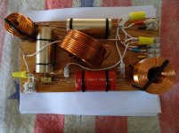
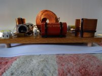
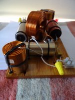
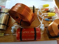
The P6 modified XO is done. Is it considered acceptable to use wire nuts instead of soldering? The wire is PTFE Style 1199 16 AWG silverplated copper wire.
Attachments

I have a few question about your XO drawing. It shows R1 as 5,6ohm and I don't see the 1.8R resistor.What a confusing thread! All is muddled! Here's what I have learned. Because I know B&W quite well.
I'm not convinced R1 at the tweeter input is 5.6R at all. It might be 0.56R! Written R56. It is seven watts for sure. 20W would be for a bass circuit. Measure it!
Tweeter is ferrofluid in the P6 and apparently has a tendency to dry out. Killing the top end. The fluid reacted with the surround glue and went solid sometimes. If that is the issue, I would clean it out altogether, but you could try replacing.
Usual internet advice to update the ageing NP capacitors. A last resort I would think, they usually work for me. But cheap entertainment.
Tweeter polarity seems to be much in doubt. It's usually positive in 6" speakers. It's actually quite hard to hear the difference in practise IMO.
Well, I looked up the P5 circuit which is all we have really. And did some simming. I doubt if it matters much the precise bass coil arrangements.
But the interesting thing is that adding a 4.7uF shunt capacitor and 1.8R resistor to the bassmid is a well known tweak on B&W 6" Kevlar speakers. Reduces cone breakup around 5kHz. People usually take the tweeter level down too. Because B&W can be a bit showroom bright.
http://rutcho.com/tweaks/01_bw_dm601s3/bw_dm601s3.html
I have a few questions about your XO drawing. Why does your P6 XO diagram show R1 as 5.6ohm while the B&W P6 XO lists R1 as 0.56? Where would the 1.8ohm resistor be in the mid bass filter? And do you know the specifications, required by XO design programs, for the three drivers in the P6?What a confusing thread! All is muddled! Here's what I have learned. Because I know B&W quite well.
I'm not convinced R1 at the tweeter input is 5.6R at all. It might be 0.56R! Written R56. It is seven watts for sure. 20W would be for a bass circuit. Measure it!
Tweeter is ferrofluid in the P6 and apparently has a tendency to dry out. Killing the top end. The fluid reacted with the surround glue and went solid sometimes. If that is the issue, I would clean it out altogether, but you could try replacing.
Usual internet advice to update the ageing NP capacitors. A last resort I would think, they usually work for me. But cheap entertainment.
Tweeter polarity seems to be much in doubt. It's usually positive in 6" speakers. It's actually quite hard to hear the difference in practise IMO.
Well, I looked up the P5 circuit which is all we have really. And did some simming. I doubt if it matters much the precise bass coil arrangements.
But the interesting thing is that adding a 4.7uF shunt capacitor and 1.8R resistor to the bassmid is a well known tweak on B&W 6" Kevlar speakers. Reduces cone breakup around 5kHz. People usually take the tweeter level down too. Because B&W can be a bit showroom bright.
http://rutcho.com/tweaks/01_bw_dm601s3/bw_dm601s3.html
I used a 0.68ohm resistor for R1 in the tweeter filter and it blocked almost everything going to the tweeter. With my ear next to the tweeter I could barely hear the cymbals on jazz CDs. Now the sound from the tweeters, without R1, is very good. Could the addition of the 5.6uF cap in the mid range filter changed the mid range response such that R1 was not needed in the tweeter filter?The P6 modified XO is done. Is it considered acceptable to use wire nuts instead of soldering? The wire is PTFE Style 1199 16 AWG silverplated copper wire.
No, more likely you would need to increase the attenuation of the tweeter to maintain a perception of low and high balance, at least according to System 7's sim here: #39
Did you measure the value of the resistor to make sure it was correct? 0.56Ω is a small value that should only attenuate the tweeter by less than 1dB, equivalent to less than one click back to 11 o'clock on the treble control of most amplifiers.
Did you measure the value of the resistor to make sure it was correct? 0.56Ω is a small value that should only attenuate the tweeter by less than 1dB, equivalent to less than one click back to 11 o'clock on the treble control of most amplifiers.
Henry, a question like that assumes that both drivers are covering some of the same frequencies. However the idea that you can turn one up to compensate for the other is a little off the mark. It's more that you should get them working at similar levels. It sounds as though you are far from where you want to be.
So I ask about the 5u6 on the midrange. Do you think it's a little small?
So I ask about the 5u6 on the midrange. Do you think it's a little small?
The resistor I put in the tweeter filter are marked Dale 1% 0.68 and using my BK Precision LCR meter they measured 0.69. I will remove the 5.6uF cap from the mid range filter. This will make it match the factory B&W P6 XO and I'll hear how the sound changes.
Last edited:
- Home
- Loudspeakers
- Multi-Way
- Three way crossover question