It likely is possible to improve the quality of the original crossover by replacing the inductors with higher 'Q' (low series resistance air core designs) and better capacitors, especially any electrolytic capacitors regardless of what their function is. Then I'd look for improvements in other obvious cost cutting in the construction, like enclosure panel damping, etc.
However to change the value of any element in the crossover will change the alignment and consequently the frequency and impulse responses of the system. This may be warranted if the original design is particularly poor, which is not something expected from premium manufacturers like B&W.
To add elements to a crossover will alter effective crossover frequencies and change the phase angle between the drivers at the crossover, which will in turn affect how the drivers sum in the crossover region, creating holes or peaks. No crossover can be designed without including the effect of frequency variable impedance of each driver as mounted in the system (the ZMA data) and the frequency dependant amplitude and phase data for the driver as mounted in the system combined with the relative acoustic centre offset as mounted on the baffle (the FRD data).
Without this data and a suitable circuit analyser like XSIM, designing a crossover is meaningless. You might result in something you prefer the sound of, but it is unlikely to be more correct. And it may make one recording sound better, but another recording sound worse if what you were doing was correcting a fault in the mastering of a favourite recording! (I used to be able to identify recordings that were mastered on JBLs versus Tannoy's versus Uries of the late '70s because of the inverse equalisation applied in response to their sound during the mastering process.) You may even accidentally reduce a source of colouration, but that's what it would be, an accident even if intentional. People who have designed loudspeaker crossovers with professional tools for many years do develop some intuition, but in any case in my experience it is unwise to rely on intuition.
Another input required for loudspeaker design is the question of what is the performance target. Personally, power response in a room takes precedence in my designs over frequency response at an arbitrary point in an anechoic space where nobody will ever listen, and this puts me at odds with just about everyone else. My target is to design speakers that can reproduce real acoustic sources approximately correctly in real acoustic spaces; I don't design loudspeakers to have a flat on-axis frequency response, although it's ideal if they can do that also.
Last edited:
I agree. it easy to disregard the signal dependant parameter shifts in crossover components subject to vibration. In an internal loudspeaker environment the vibration forces on components can be quite extreme especially at mechanical resonances.Putting the crossover outboard means put it out of the enclosure, right? That's an improvement! But well away, possibly isolated by vibrations et all...
Well, those are 3 way! And not in the 85 dB league! When I say 'put it in the picture', I really meant :show the speaker!
The distance between wf and mid...see the value of the inductor (subwoofer league)
Here are the B&W P6 specifications
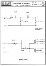
Bass Alignment Twin 4th Order vented box, Crossover Frequency 150Hz, 3kHz, Frequency Response 30Hz to 20kHz +- 2dB, Sensitivity 90dB spf(2.83V 1m). The schematic represents the original XO. The photo shows the P6 speakers


Bass Alignment Twin 4th Order vented box, Crossover Frequency 150Hz, 3kHz, Frequency Response 30Hz to 20kHz +- 2dB, Sensitivity 90dB spf(2.83V 1m). The schematic represents the original XO. The photo shows the P6 speakers
Last edited:
Hi, I saw the specifications the other day... What puzzled me was the value of the LP(low pass) inductor, so my mental wandering on sensitivity and efficiency of the system. The schematic above has the tweeter path components put wrongly.
Diyaudio member 5th Element used that midrange in his experiments...(the yellow one with not-that-pronounced surround, so a pure midrange)
Diyaudio member 5th Element used that midrange in his experiments...(the yellow one with not-that-pronounced surround, so a pure midrange)
I also thought C2 in the tweeter filter was in an odd location. However I followed the component + locations on the actual P6 crossover and it seems the + from the amp is connected to R1 which connects to C1. Then the other lead of C1 and leads of L1 and C2 are all soldered to a + section of the PCB. The other lead from C2 is soldered to a - section of the PCB. I put paper circles, marked + and -, on appropriate PCB sections. The photos show where C1, L1 and C2 connect to the PCB. That is what led me draw the tweeter filter as I did. Please let me know if my interpretation is wrong?


Well, the plus and minus in loudspeakers indicate the correct phase, so where's the joint of C1, L and C2, there's no driver attached so it's meaningless.
Sometimes the driver needs to be phase reversed so you'll see the minus instead of plus. It goes together with filter theory as every order of a filter brings 90 degree phase rotation... Tvrge3k and Johnmath already explained it very well
Sometimes the driver needs to be phase reversed so you'll see the minus instead of plus. It goes together with filter theory as every order of a filter brings 90 degree phase rotation... Tvrge3k and Johnmath already explained it very well
It is really simple to know what sections of a PCB are plus or minus. The speaker wire connections are shown in the last B&W photo of the crossover diagram and also the the wire connectors on the back of the speaker are marked + and - .So with a multimeter it is fairly easy to follow the positve and negative paths on the PCB
My first step in trying to understand the origninal B&W P6 XO filters was to look at the attached photo. That allowed me to know where the plus and minus for the low filters and the plus and minus high filter pass started. I then took the PCB off the mounting block and started to trace the filter paths using a mulitmeter set to the continuity position.

Hi, as I said, plus and minus it's just a convention to say positive phase or negative. You can say red or black...
Example: put the lower woofer mounted reversed so you see the magnet. Normally the cone goes forward but in this case to respect phase you should reverse the contacts.
Example: put the lower woofer mounted reversed so you see the magnet. Normally the cone goes forward but in this case to respect phase you should reverse the contacts.
I really don't understand your remarks. I was simply trying to determine what components where in what filters and how they wre connected, in series or parallel.
The difficulty comes from not understanding implied meanings that would be apparent if you knew more about the physics of electronic components and crossovers. The circuit as you have drawn it will not work as it will not pass the high frequencies to the tweeter. If it is drawn correctly, then someone has fiddled with the crossover and I doubt the speakers would be much use for listening to music.
The (-) terminal of the connection panel on the rear of the loudspeaker does not necessarily connect to the (-) of the tweeter, it often connects to the (+) terminal instead. The correct connection (+) or (-) is a function of the position of the tweeter and midrange relative to each other, as well as the crossover frequency, and the topology and order of the crossover design, and the measured FRD and ZMA performance data for each driver measured in position on the baffle. The objective is (usually) to have the drivers sum and provide ½ the energy each at the crossover frequency, and that might mean that one of them is reverse connected relative to the input terminals.
I am intrigued by the large inductor. It looks like a P-core with discs from Jantzen Audio, and therefore unlikely to be original, which begs the question: what other changes have been made?
That is correct. I bought the speakers new from a B&W dealer many years ago. And the speakers have always sounded very good to my ears. I'm still stumped about C2 input lead connected to the + leg and its output leg connected to the - leg.
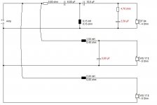
this is the crossover for the B&W P3 as I make it out from the service manual, drawn with XSim. The exclamation marks on the speakers are there because no FRD or ZMA data has been entered for the speakers as I don't have a P3 to measure the drivers. Note that the tweeter polarity is inverted, and by mistake I have drawn the crossover as if the (-) input link is connected.

Last edited:
Actually I have made another mistake (typical day for me!) The PCB layout in the B&W service manual is not very clear, but reviewing photos of P6 crossovers clarifies that inductor L2 for the L/L (lower low frequency driver) connects to the righthand side of L1 (≡ to the (+) terminal of the U/L driver), not the LF input terminal.
You did wrong. The correct crossover is what johnmath designed. It is a 3rd order electrical filter on the tweeter, connected with reversed polarity, and 1st order electrical filter on the mid a and bass. Note that there is no LP filter on the mid, the design evidently uses the natural rolloff of the mid enclosure to reach the target, the drawback can be a reduced power handling. Or, as a second thought, it is a sort of a 2.5 way design with different drivers for the .5 part (something unusual but doable). The tip here is a port also for the "mid" driver.My first step in trying to understand the origninal B&W P6 XO filters was to look at the attached photo. That allowed me to know where the plus and minus for the low filters and the plus and minus high filter pass started. I then took the PCB off the mounting block and started to trace the filter paths using a mulitmeter set to the continuity position.
That said, what let you think that you can do better than the B&W original crossover, changing components value and crossover topology without measuring? The proposed crossover in post #1 has the tweeter connected inverted, and a lower crossover point for the mid and bass, this will ensure holes in the FR.
Ralf
What a confusing thread! All is muddled! Here's what I have learned. Because I know B&W quite well.
I'm not convinced R1 at the tweeter input is 5.6R at all. It might be 0.56R! Written R56. It is seven watts for sure. 20W would be for a bass circuit. Measure it!
Tweeter is ferrofluid in the P6 and apparently has a tendency to dry out. Killing the top end. The fluid reacted with the surround glue and went solid sometimes. If that is the issue, I would clean it out altogether, but you could try replacing.
Usual internet advice to update the ageing NP capacitors. A last resort I would think, they usually work for me. But cheap entertainment.
Tweeter polarity seems to be much in doubt. It's usually positive in 6" speakers. It's actually quite hard to hear the difference in practise IMO.
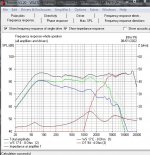
Well, I looked up the P5 circuit which is all we have really. And did some simming. I doubt if it matters much the precise bass coil arrangements.
But the interesting thing is that adding a 4.7uF shunt capacitor and 1.8R resistor to the bassmid is a well known tweak on B&W 6" Kevlar speakers. Reduces cone breakup around 5kHz. People usually take the tweeter level down too. Because B&W can be a bit showroom bright.
http://rutcho.com/tweaks/01_bw_dm601s3/bw_dm601s3.html
I'm not convinced R1 at the tweeter input is 5.6R at all. It might be 0.56R! Written R56. It is seven watts for sure. 20W would be for a bass circuit. Measure it!
Tweeter is ferrofluid in the P6 and apparently has a tendency to dry out. Killing the top end. The fluid reacted with the surround glue and went solid sometimes. If that is the issue, I would clean it out altogether, but you could try replacing.
Usual internet advice to update the ageing NP capacitors. A last resort I would think, they usually work for me. But cheap entertainment.
Tweeter polarity seems to be much in doubt. It's usually positive in 6" speakers. It's actually quite hard to hear the difference in practise IMO.
Well, I looked up the P5 circuit which is all we have really. And did some simming. I doubt if it matters much the precise bass coil arrangements.
But the interesting thing is that adding a 4.7uF shunt capacitor and 1.8R resistor to the bassmid is a well known tweak on B&W 6" Kevlar speakers. Reduces cone breakup around 5kHz. People usually take the tweeter level down too. Because B&W can be a bit showroom bright.
http://rutcho.com/tweaks/01_bw_dm601s3/bw_dm601s3.html
Attachments

Thanks for the info. Last night I did a bit more checking the high pass filter with the multimeter and also found the tweeter polarity is to be inverted.this is the crossover for the B&W P3 as I make it out from the service manual, drawn with XSim. The exclamation marks on the speakers are there because no FRD or ZMA data has been entered for the speakers as I don't have a P3 to measure the drivers. Note that the tweeter polarity is inverted, and by mistake I have drawn the crossover as if the (-) input link is connected.
View attachment 1012942
- Home
- Loudspeakers
- Multi-Way
- Three way crossover question