AndrewT -- I need it in ohms
Let's make a fix, within a defined application. I'd sure love to see what your recommendations are--when confined into the boundries of the following. . .
Input:
The source is a worst case scenerio that varies.
There will be no change in the input circuit of the chart except for your choice of potentiometer at the signal input. Please specify
NFB:
There will be 47uf in the NFB
There will be either 1k or 1.5k in the NFB Please specifiy.
You choose the resistance value of the one remaining part. Please specify.
Spike:
The layout of the chart provides a many times boost in available headroom--which may be misused during exuberant 140watt plus usage and exceed thermals without the protection of the spike system in full effect.
You have probably found the control--assuming it was the "voltage across 47uf" that allows more headroom and less Spike. However, my approach is overkill. The issue is now both thermals and headroom, which should be made scalable.
Output:
You can choose between the chart. . .
Or you can choose two simultaneous zobels--one of which is in reverse polarity to the other.
You can specificy ESR1 polypropylene, ESR7 mylar, or ESR10+ polyester along with any additional resistance values.
Finally, what specific resistance value (!!!) do you recommend for the one remaining part, the "Rf" resistor, in the NFB?
Is that, perhaps, 76k? Please specify your recommendation as a resistance value.
I don't currently have enough baselines, documents, and instructionals collected to be able to understand your recommendation given in milleseconds, although the effects of matched speeds make perfect sense.
Thank you!!!
AndrewT said:the high pass filter on the input passes more low frequency than the NFB can handle. The voltage across the 47uF will be significant and lead to some odd sounding results.
The input filters (both HF and LF) should define the bandwidth of the amplifier. The NFB should be set up at a slightly lower frequency.
I suggest you alter the 4.7uF + 56k =263mS to around 80 to 90mS and increase the NFB from 47mS (47uF + 1k) to around 130 to 150mS.
However the 4.7uF is not in isolation. The DC blocking capacitor in the source equipment is also in series with the power amplifier DC blocking cap. If both the source and the receiver have caps fitted then your time constant must take account of this topology.
Finally,
fit an RF (low pass) filter to the power amplifier input.
Let's make a fix, within a defined application. I'd sure love to see what your recommendations are--when confined into the boundries of the following. . .
Input:
The source is a worst case scenerio that varies.
There will be no change in the input circuit of the chart except for your choice of potentiometer at the signal input. Please specify
NFB:
There will be 47uf in the NFB
There will be either 1k or 1.5k in the NFB Please specifiy.
You choose the resistance value of the one remaining part. Please specify.
Spike:
The layout of the chart provides a many times boost in available headroom--which may be misused during exuberant 140watt plus usage and exceed thermals without the protection of the spike system in full effect.
You have probably found the control--assuming it was the "voltage across 47uf" that allows more headroom and less Spike. However, my approach is overkill. The issue is now both thermals and headroom, which should be made scalable.
Output:
You can choose between the chart. . .
Or you can choose two simultaneous zobels--one of which is in reverse polarity to the other.
You can specificy ESR1 polypropylene, ESR7 mylar, or ESR10+ polyester along with any additional resistance values.
Finally, what specific resistance value (!!!) do you recommend for the one remaining part, the "Rf" resistor, in the NFB?
Is that, perhaps, 76k? Please specify your recommendation as a resistance value.
I don't currently have enough baselines, documents, and instructionals collected to be able to understand your recommendation given in milleseconds, although the effects of matched speeds make perfect sense.
Thank you!!!

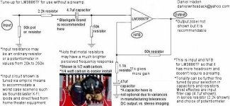
Diagram 2! 😉
Okay! I finally got National's spreadsheet.
Here's a LM3886 chart that doesn't blink anything into the orange, yet it should sound the same as the first mod.
Does anyone know if there's a difference in heat (thermals) between chart #1 and chart #2? Or does any greater gain also generate greater heat?
Now, the question is how to tune up LM1875 to sound the same as big brother for use in surround sound application (with both).
First, since the little one changes tone (temperment) with voltage (unlike big brother), I guess we'll have to specify 30+30 volts DC rails (a 36vct transfo)? Or, could I safely use higher?
Attachments
Re: AndrewT -- I need it in ohms
I have already replied to your Email sent via DIYaudio.
Hi Daniel,danielwritesbac said:
Let's make a fix, within a defined application. I'd sure love to see what your recommendations are-
I have already replied to your Email sent via DIYaudio.
dolby surround with LM1875
Well, that was the most amazing email ever. I actually became dizzy, so I printed it. However, some of it made really good sense when physically applied.
Andrew, can you double-check the following assumptions? . . .
On the parts that didn't require specificing the power supply or nature of the source, I got news that the input section isn't "full draft" and in fact that a capacitor is missing from it.
Location unknown.
Value probably 330PicoFareds.
Task is RF filter.
One leg goes to ground.
The other physical connection is unspecified.
Where does it go?
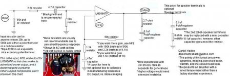
Thank you for the talk about NFB vs power supply. I'll fix the chart. An annotation (sidenote) has a mismatch for some applications, although it isn't harmful to Brian's kit or K50--I will delete the annotation to further generalize the application.
I'm sorry that I can't put 630R or 680R into the NFB. Physical measure resolves that 1k and 1.5k are valid, "between a rock and a hard place" of either DC offset or setting off Spike too early.
We can negotiate any optimized NFB values with LM1875 and TDA7294, but not with LM3875, LM3886, and LM4780 that contain extensive, audiable, limiting circuitry with absent documention on controlling its sensitivity.
Between these amplifier models, and "readily available" the power structures of Brian's and K50 match up closely. This can make ease for the end user, and for me when trying to match the tonalities together for a gainclone surround sound plan.
Now, of course, we need "matching intent" for LM1875. Let's specificy that we're going to mod K50. Let's specify voltage.
Andrew, do you know what an optimally powerful voltage could be for LM1875? It needs to come to within 4db of LM3886 chart#2. Its supposedly possible to do that.
Now for LM1875 surround channels:
I tested 30+30 volts DC, and the little chip on stock K50 was graceful thermals despite a 4 ohm speaker. When the input filter cap was increased in size, it lost power down to a perceived 6 watts although its presentation was better.
This needs a plan.
We need a wide open input bandwidth because "source" is considered worst case scenerio.
Howabout:
20k pot to, 2.2k to, 3.3uf to, 10k load, to chip, for input?
Where does that RF shunt cap go??
So, for zero losses at 45hz, and siginificant gain, what does the NFB look like? (Ohms and microfareds please).
Thank yoooooooooooo!!
Well, that was the most amazing email ever. I actually became dizzy, so I printed it. However, some of it made really good sense when physically applied.
Andrew, can you double-check the following assumptions? . . .
On the parts that didn't require specificing the power supply or nature of the source, I got news that the input section isn't "full draft" and in fact that a capacitor is missing from it.
Location unknown.
Value probably 330PicoFareds.
Task is RF filter.
One leg goes to ground.
The other physical connection is unspecified.
Where does it go?
Thank you for the talk about NFB vs power supply. I'll fix the chart. An annotation (sidenote) has a mismatch for some applications, although it isn't harmful to Brian's kit or K50--I will delete the annotation to further generalize the application.
I'm sorry that I can't put 630R or 680R into the NFB. Physical measure resolves that 1k and 1.5k are valid, "between a rock and a hard place" of either DC offset or setting off Spike too early.
We can negotiate any optimized NFB values with LM1875 and TDA7294, but not with LM3875, LM3886, and LM4780 that contain extensive, audiable, limiting circuitry with absent documention on controlling its sensitivity.
Between these amplifier models, and "readily available" the power structures of Brian's and K50 match up closely. This can make ease for the end user, and for me when trying to match the tonalities together for a gainclone surround sound plan.
Now, of course, we need "matching intent" for LM1875. Let's specificy that we're going to mod K50. Let's specify voltage.
Andrew, do you know what an optimally powerful voltage could be for LM1875? It needs to come to within 4db of LM3886 chart#2. Its supposedly possible to do that.
Now for LM1875 surround channels:
I tested 30+30 volts DC, and the little chip on stock K50 was graceful thermals despite a 4 ohm speaker. When the input filter cap was increased in size, it lost power down to a perceived 6 watts although its presentation was better.
This needs a plan.
We need a wide open input bandwidth because "source" is considered worst case scenerio.
Howabout:
20k pot to, 2.2k to, 3.3uf to, 10k load, to chip, for input?
Where does that RF shunt cap go??
So, for zero losses at 45hz, and siginificant gain, what does the NFB look like? (Ohms and microfareds please).
Thank yoooooooooooo!!
Re: dolby surround with LM1875
The RF attenuation capacitor is fitted after the series R and can go in parallel to the last resistor that sources the current to feed the input offset current.
Taking your last example.
20k pot
2k2 series in input feed
3u3F series in input feed
10k input to signal ground
add a 330pF in parallel to the 10k to act as an RF filter. This gives a 0.7uS time constant. You may want to experiment with this value until you have achieved best sound for that amp and equipment combination.
However, 3u3F and 10k for Zin removes some of the bass signal.
Is there a DC blocking cap fitted into any of your source equipment?
Second "however", 20k pot gives a maximum Rsource of 5k feeding your Zin=10k+2k2 =12k2. This breaks the usual rule of Rs<<Zin
I recommend 20times lower, but 5 to 10times can just about work.
The pot value also interacts with the RF filter capacitor and will roll off more treble than intended.
I do not like to see high Rs feeding any amplifier, be it an opamp, pre-amp, or power amp, unless it can be shown that high Rs does not interfere with the audio signal.
Now for NFB.
If you keep the sole DC block at 3u3F with Zin=10k then RC =33mS.
NFB >=46mS. Your 1k0 and 47uF meets this requirement.
I have extracted this short section for a reply. The rest is just gobbledegook. I cannot follow the reasoning nor the results you are reporting.danielwritesbac said:............. that a capacitor is missing from it.
Location unknown.
Value probably 330PicoFareds.
Task is RF filter.
One leg goes to ground.
The other physical connection is unspecified.
Where does it go?
.....................We need a wide open input bandwidth .................
Howabout:
20k pot to, 2.2k to, 3.3uf to, 10k load, to chip, for input?
Where does that RF shunt cap go??
...............what does the NFB look like?
The RF attenuation capacitor is fitted after the series R and can go in parallel to the last resistor that sources the current to feed the input offset current.
Taking your last example.
20k pot
2k2 series in input feed
3u3F series in input feed
10k input to signal ground
add a 330pF in parallel to the 10k to act as an RF filter. This gives a 0.7uS time constant. You may want to experiment with this value until you have achieved best sound for that amp and equipment combination.
However, 3u3F and 10k for Zin removes some of the bass signal.
Is there a DC blocking cap fitted into any of your source equipment?
Second "however", 20k pot gives a maximum Rsource of 5k feeding your Zin=10k+2k2 =12k2. This breaks the usual rule of Rs<<Zin
I recommend 20times lower, but 5 to 10times can just about work.
The pot value also interacts with the RF filter capacitor and will roll off more treble than intended.
I do not like to see high Rs feeding any amplifier, be it an opamp, pre-amp, or power amp, unless it can be shown that high Rs does not interfere with the audio signal.
Now for NFB.
If you keep the sole DC block at 3u3F with Zin=10k then RC =33mS.
NFB >=46mS. Your 1k0 and 47uF meets this requirement.
It's not just you.Gopher said:doe anyone here understand a word daniel is saying or is it just me?
Daniel, can I get some of those drugs you're on? I'd like a break from reality too.
Re: Re: dolby surround with LM1875
But you did! I wanted to conserve the LM1875 by cutting the bass somewhere around 40hz to 45hz.
I did that in the wrong place, it seems. How do it do it within the NFB alone?
AndrewT said:I have extracted this short section for a reply. The rest is just gobbledegook. I cannot follow the reasoning nor the results you are reporting.
But you did! I wanted to conserve the LM1875 by cutting the bass somewhere around 40hz to 45hz.
I did that in the wrong place, it seems. How do it do it within the NFB alone?
paulb said:
It's not just you.
Daniel, can I get some of those drugs you're on? I'd like a break from reality too.
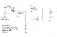
I'm making a surround sound with LM1875 rear channels, and source is assumed worst case scenerio.
But, if you'd like a break from reality, try measuring with an ohmmeter to find the ac signal of a given resistor. Or try measuring any audio application for a capacitor with a capacitance meter.
Neither can resolve an answer. An incomplete measure is biased towards its findings, but biased away from an actual application.
There's a break from reality for ya!
The second one was a reply to Paul. It was an illustration, not a recommended practice by any means.
The first, I'd like to conserve the power of LM1875 by having it operate between 43hz and 22khz--restricted to within those boundries and with fairly high gain. Help?
The point it to confine the LM1875 into a "most useful" bandwidth so that it can make much more of "most useful" output power.
This is intended as a power boost.
To use filter functions, treat the LM1875 just like any opamp and calculate your desired filter function with TI filterpro (Oh, any Spice will work to, but I think that no one her, me to, can handle this...)
An externally hosted image should be here but it was not working when we last tested it.
weissi said:To use filter functions, treat the LM1875 just like any opamp and calculate your desired filter function with TI filterpro (Oh, any Spice will work to, but I think that no one her, me to, can handle this...)
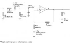
Well, that'll keep me busy. The answers provided are so unlike the actual circuit. Its a great tool, but how do I relate its answers to the above photograph so that I can insert the correct values. P.S. shoot for 30hz, not 43.
Daniel, go to the public library and get:
Walter G. Jung
IC Op-Amp Cookbook
or
Audio IC Op-Amp Applications
or,or
Go to the Analog Devices web-page and down load:
Op-Amp Applications edited by Walt Jung
Walter G. Jung
IC Op-Amp Cookbook
or
Audio IC Op-Amp Applications
or,or
Go to the Analog Devices web-page and down load:
Op-Amp Applications edited by Walt Jung
Kevin Graf said:Daniel, go to the public library and get:
Walter G. Jung
IC Op-Amp Cookbook
or
Audio IC Op-Amp Applications
or,or
Go to the Analog Devices web-page and down load:
Op-Amp Applications edited by Walt Jung
Good suggestions.
And here's the direct link to the free download of Jung's "Op Amp Applications Handbook":
http://www.analog.com/library/analogDialogue/archives/39-05/op_amp_applications_handbook.html
I think that you will really like this book, Daniel.
Dolby Surround Sound rear channels
Oh I really like that book! Thank you!
I do still need a baseline from folks wiser than myself.
I seemed to have skipped a few steps. My apologies.
Its just enthusiasm and that I'm so eager to complete the dolby surround sound gainclone amp.
Step1
What I need first is to boost the gain (NFB) of LM1875 so that enhanced SPL doesn't involve overdriving the input.
This should be in the form of an easy, beginner level mod to the common K50 kit.
A worst-case source should be anticipated, bearing in mind that someone (not me) is going to ask an Ipod or X-FI to drive 5 amplifiers directly.
Here is an example of that step completed on the LM3886 kit--the main (front) channels of the gainclone surround sound amp.
The least effective empirics have been reduced/subtracted.
What's a good starting place to begin this, Step1, with LM1875's K50 kit?
Thanks again!
Attachments
Hi Daniel,
It might be better to have a resistance directly before the 330 pF cap, since it should be configured to be part of a passive low-pass RF filter. I do also think that, for non-inverting chipamps at least, the 330 pF cap should be the last thing before the chipamp input (as you have shown), and should be as close as possible to the input pin. With 2.2k before the 330 pF, the -3dB filter corner frequency would be about 219.2 kHz (i.e. 1/2/Pi/R/C, in "calculator" format), which should be OK.
Note, too, that many people place a smaller, higher-quality capacitor in parallel with the input DC-blocking capacitor. Polystyrene might be very good. Mouser.com has them.
Also, conceptually, your 50k potentiometer should be drawn as a voltage divider, i.e. two R's to ground, and a third wire (the pot's wiper terminal) connected between the resistors. Usually, you would have the signal coming from between the resistors (from the wiper), UNLESS you're only using the pot to vary the input impedance, and not to "directly" change the volume. Either way, pots have three connections, which should be shown.
For "worst-case" source impedances, you'll probably want a high input impedance. Maybe you should consider using a simple opamp (or FET) buffer stage, for the input. That way, you'd get the extremely high input impedance that is very desirable, and would also get the extremely low buffer output impedance as the source impedance for the chipamp, which is very desirable. And then you also wouldn't have to worry about changing the chipamp's characteristics due to a changing input impedance.
For even MORE fun, and to get _much_ better performance from a chipamp (not to mention many more "controllability" and "tuning" options), put an opamp before the chipamp but take the opamp's negative feedback from the chipamp's output. (Jung has "composite" amps, like that, in the linked-to book, as well. They have many advantages.)
To better play with all of this (at least for your next project, if this one just can't wait), I recommend that you download the free LTspice simulator software, from http://ltspice.linear.com/software/swcadiii.exe . [However, you'll find that there aren't any good available spice models for National's chipamps. But I've had very good luck using TI.com's OPA541 chipamp's spice model (the "E" model-version), for general types of chipamp simulations. You can also get that model from my spice-modeling webpage, at http://www.fullnet.com/~tomg/gooteesp.htm . (And if you want to dispense with the DC-blocking capacitors, I also have a basic DC Servo circuit, there, and the LTspice files for it.)]
- Home
- Amplifiers
- Chip Amps
- Thoughts On LM1875 Gainclones